Chapter 12. How to Use Position/Torque Servo
12-1
12. How to Use Position/Torque Servo
12.1 Power Supply Wiring
For wiring, see "3.3 Main Circuit Terminal Board Wiring".
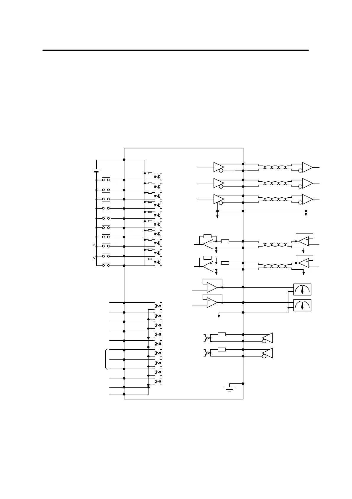
12.2 CN1 Wiring
Make wiring as follows to use FDA5000 as the position/torque control mode.
/PAO
PAO (7)
(32)
/PBO
(6)
(31)
/PZO
PZO (5)
(30)
+
MONIT1
MONIT2
(3)
(2)
SPDIN
(27)
GND
TRQIN (28)
GND
+
+
GND
GND [Note1]
SVONEN(18)
(38)
ALMRST
(41) PI/P
(14) TLIM
(43)
SPD1/
(17)
(15) CCWLIM
(40) CWLIM
(39) ESTOP
+24V
+24VIN(49)
Servo enable
CCW limit
CW limit
Emergency stop
Cumulative pulse clear
[Note3] Select PI/P
[Note3] Analog torque limit
(24) GND24
(25) GND24
A_CODE0
A_CODE1
A_CODE2
(45)
(44)
(19)
ZSPD(47)
ALARM(20)
(22)
(21) RDY
BRAKE(48)
Servo ready
Zero speed
Brake activate
Alarm status
Alarm code
10K
10K
(42) TYPE
TRQOUT(46)
Torque under limit
PBO
-10 ~ +10V
-4 ~ +4V
4.7K
[Note1]
[Note1]
+
+
10K
10K
-10 ~ +10V
[Note1]
+
-4 ~ +4V
F.G
(50)
[Note2]
300
(11)
(10)
(9)
(12)
PPFIN
PFIN
PPRIN
PRIN
300
Alarm reset /
Select position/torque
(On / Off)
/CLR
GEAR1
SPD2/
GEAR2
[Note3] In speed
INPOS
Select speed /
Select electronic gear
Note1 : Select GND terminal from among 1,8,26,33,34 and 36.
Note2 : Use CN1 shield wire to ground the F.G.(Frame Ground) terminal.
Note3 : Available for position mode.
*Note)If used in the
Open Collector System
short-circuit the
PPFIN(11), PPRIN(9)
terminal.
(See section 3.4.3)
Position command pulse input
(Line Drive : SN75174)