Chapter 8. How to Use Position Servo
8-1
8. How to Use Position Servo
8.1 Power Supply Wiring
For wiring, see "3.3 Main Circuit Terminal Board Wiring".
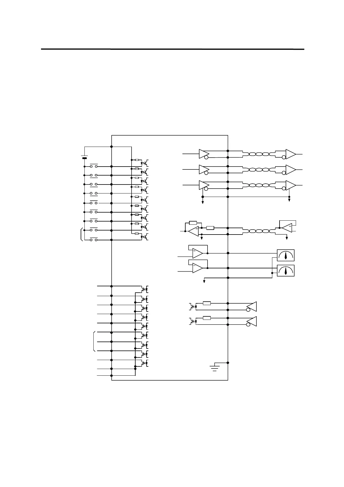
8.2 CN1 Wiring
Make wiring as follows to use FDA5000 as the position control mode.
/PAO
PAO (7)
(32)
/PBO
(6)
(31)
/PZO
PZO (5)
(30)
+
MONIT1
MONIT2
(3)
(2)
TRQIN (28)
GND
GND
GND [Note1]
SVONEN(18)
+24V
+24VIN(49)
Servo enable
(24) GND24
(25) GND24
A_CODE0
A_CODE1
A_CODE2
(45)
(44)
(19)
ZSPD(47)
ALARM(20)
INPOS(22)
(21) RDY
BRAKE(48)
Servo ready
In position
Zero speed
Brake activate
Alarm status
Alarm code
Note1 : Select GND terminal from among 1,8,26,33,34 and 36.
Note2 : Use CN1 shield wire to ground the F.G.(Frame Ground) terminal.
TRQOUT(46)
Torque under limit
PBO
-4 ~ +4V
4.7K
[Note1]
+
+
10K
10K
-10 ~ +10V
[Note1]
+
-4 ~ +4V
(38)
ALMRST
(41) PI/P
(14) TLIM
(43) GEAR1
(17) GEAR2
(15) CCWLIM
(40) CWLIM
(39) ESTOP
CCW limit
CW limit
Emergency stop
Alarm reset /
Select PI/P
Analog torque limit
Select speed
/CLR
F.G (50)
[Note2]
300
(11)
(10)
(9)
(12)
PPFIN
PFIN
PPRIN
PRIN
Position command pulse input
(Line Drive : SN75174)
*Note)If used in the
Open Collector System
short-circuit the
PPFIN(11), PPRIN(9)
terminal.
(See section 3.4.3)
300
Cumulative pulse clear