Chapter 7. How to Use Speed Servo
7-5
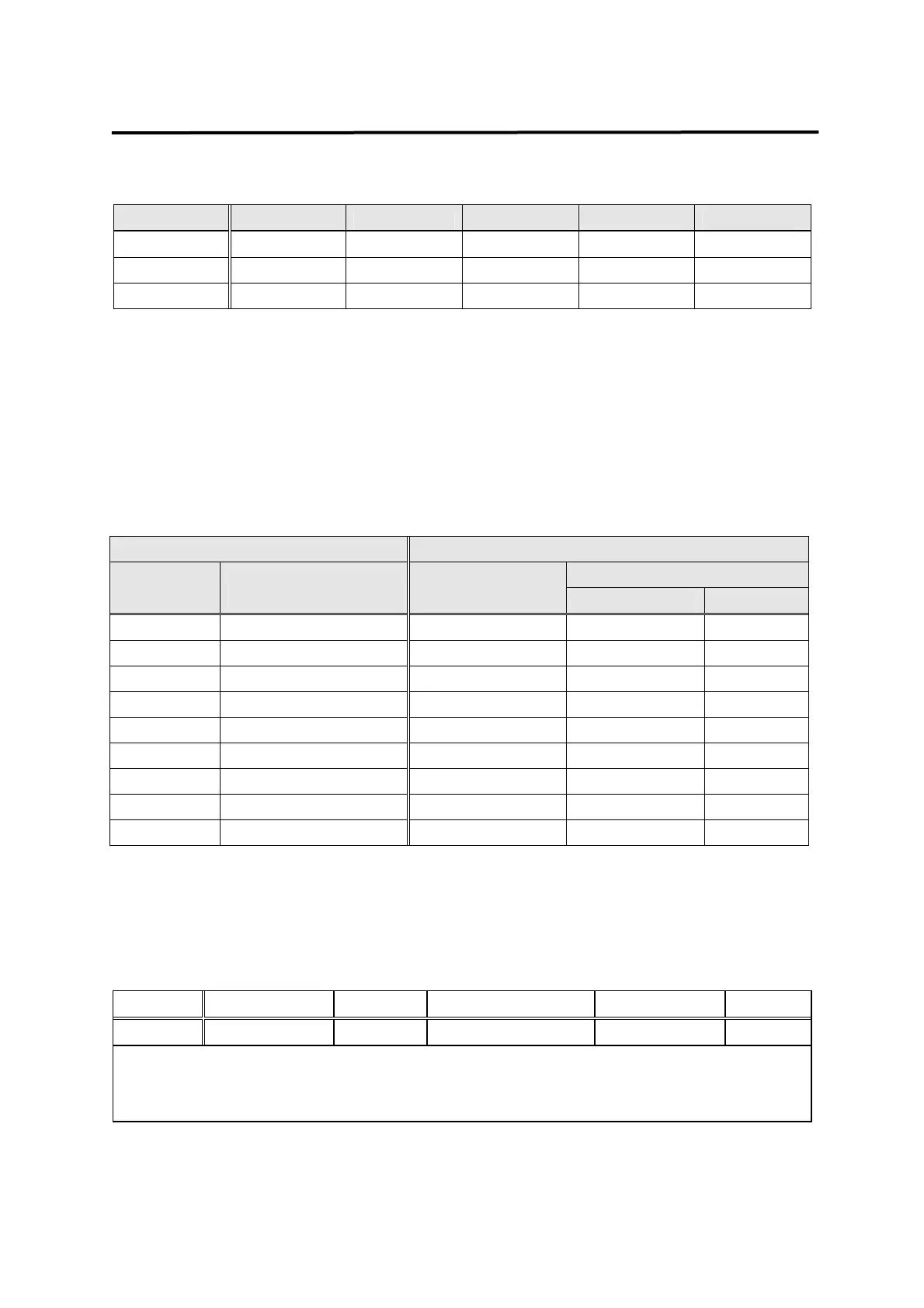
☞ Set (P2-23) range according to approximate inertia ratio.
Inertia ratio Set value Inertia ratio Set value Inertia ratio Set value
1 ~ 3
1
10 ~ 25
4
100 ~ 300
7
2 ~ 10
2
15 ~ 100
5
200 ~ 400
8
3 ~ 15
3
25 ~ 200
6
300 ~ 500
9
☯ Inertia ratio = (Motor inertia + load inertia) / Motor inertia
☞ Decelerating/accelerating for about 5 times after turning ON autotuning (P2-24) will
allow the inertia value to be stored in (P2-22).
☞ Turn off autotuning (P2-24).
b) Adjusting control system gains
☞ Manually input inertia ratio (P2-22) if the inertia ratio is known.
☞ Adjust the following value according to inertia ratio.
Inertia ratio Set value
SC I TC (P2-04) Motor
60, 80
Motor
greater than 130
SC LOOP Gain
(P2-03)
Recommended Minimum
1 500 20 6
2 350 30 9
3 290 35 11
5 1 220 45 14
10 2 160 60 19
20 3 110 90 27
50 5 70 140 42
100 10 50 200 60
20 30 300 100
☯ If the SC Loop gain is too low, vibration occurs and response becomes fast if it is high,
but vibration occurs if the gain is excessively high. Response becomes fast if SCI TC is
reduced, but overshoot occurs if it is reduced excessively.
7.4.4 Setting feedback delay
Menu Menu name Unit Display range Initial value Mode
*P3-17 FDELAY ms 0.0 ~ 100.0 0.0 SPT
Adjust FDELAY (P3-17) when noise occurs due to motor vibration.
Use FDELAY value within the speed integrating time constant [SCI TC] (P2-04) value.
Recommended value = [ SC I TC ] / 5 ~ [ SC I TC ] / 2