7. Connection with host controller
7-3
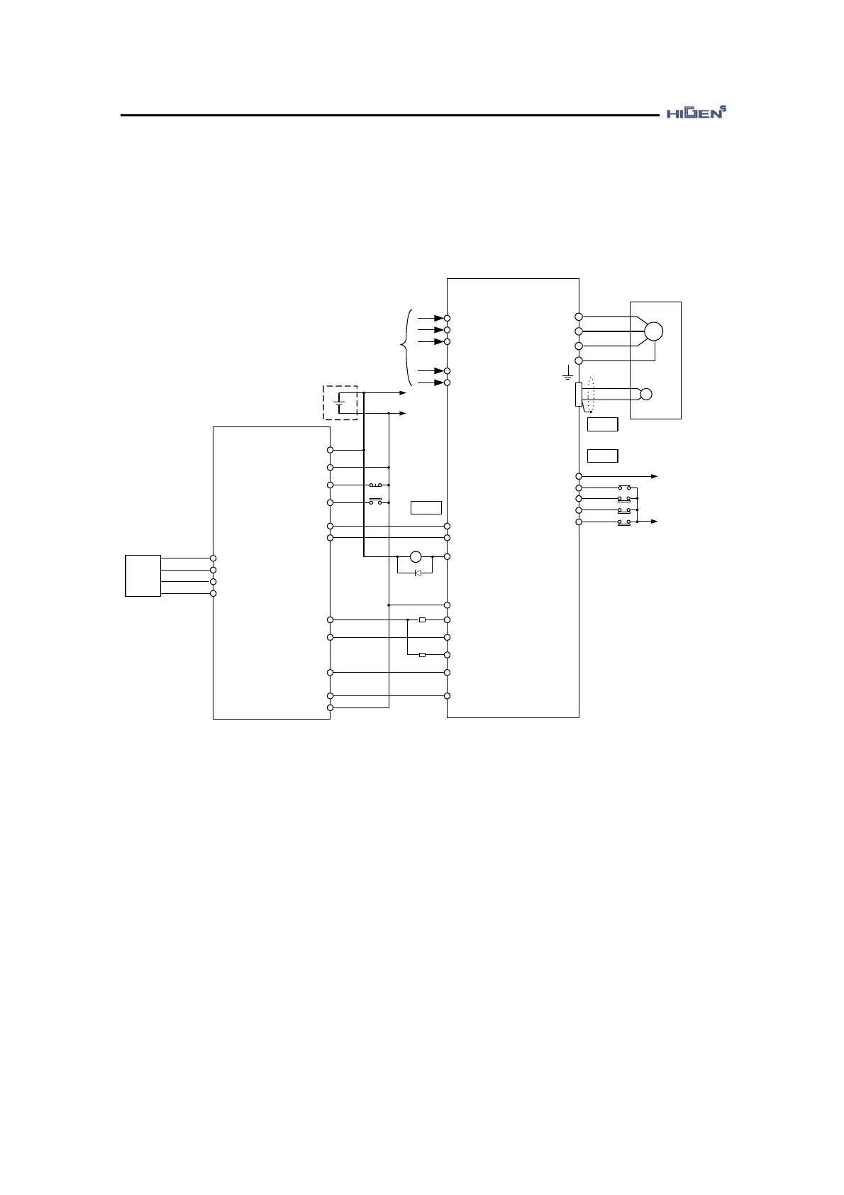
Connect with LS Industrial System MASTER-K position decision unit K7F-POPA
This is an example of position control mode servo system operation.
FDA7000
23
5
11
9
25
CLEAR
RP
FP
ZL
2
4, 5
R
S
T
r
t
PPFIN
PFIN
PPRIN
PRIN
PZO
/PZO
MASTER-K
K7F-POPA
M
U
V
W
FG
SERVO MOTOR
CN2
CN1
AC
200 ~ 230V
50/60 Hz
+24V
GND24
+
-
+24V
CN1
PLSCLR
10
1, 4, 5, 21
19
22
GND24V
Emergency
Stop
DOG
+24V
18
13
49
38
17
GND24
CCWLIM/PTQLIM
SVONEN
CWLIM/NTQLIM
ESTOP
GND24
24, 25
11
10
9
12
14
1Ry
ALARM
PG
1/2W,1.5K
24 COM
30
5
ZCOM
+24V
Manual
PULSE
DC 5~12V
MPGA
MPGA-C
MPGB
MPGB-C
8
16
7
15
1/2W,1.5K
20
+24VIN
(Note) After connecting the power, it takes about 1-2 seconds until the alarm signal leads
to normal operation. Consider this when designing the power connection sequence.
Also the alarm signal operates alarm detection relay 1Ry to turn on the main circuit
power of servo drive.
It only has the signals related to LS Industrial Systems K7F-POPA and FDA7000 Series
(Note) The above connection is only shown in case of P07-01=27(Position control mode)