2. Wiring and connection
2-29
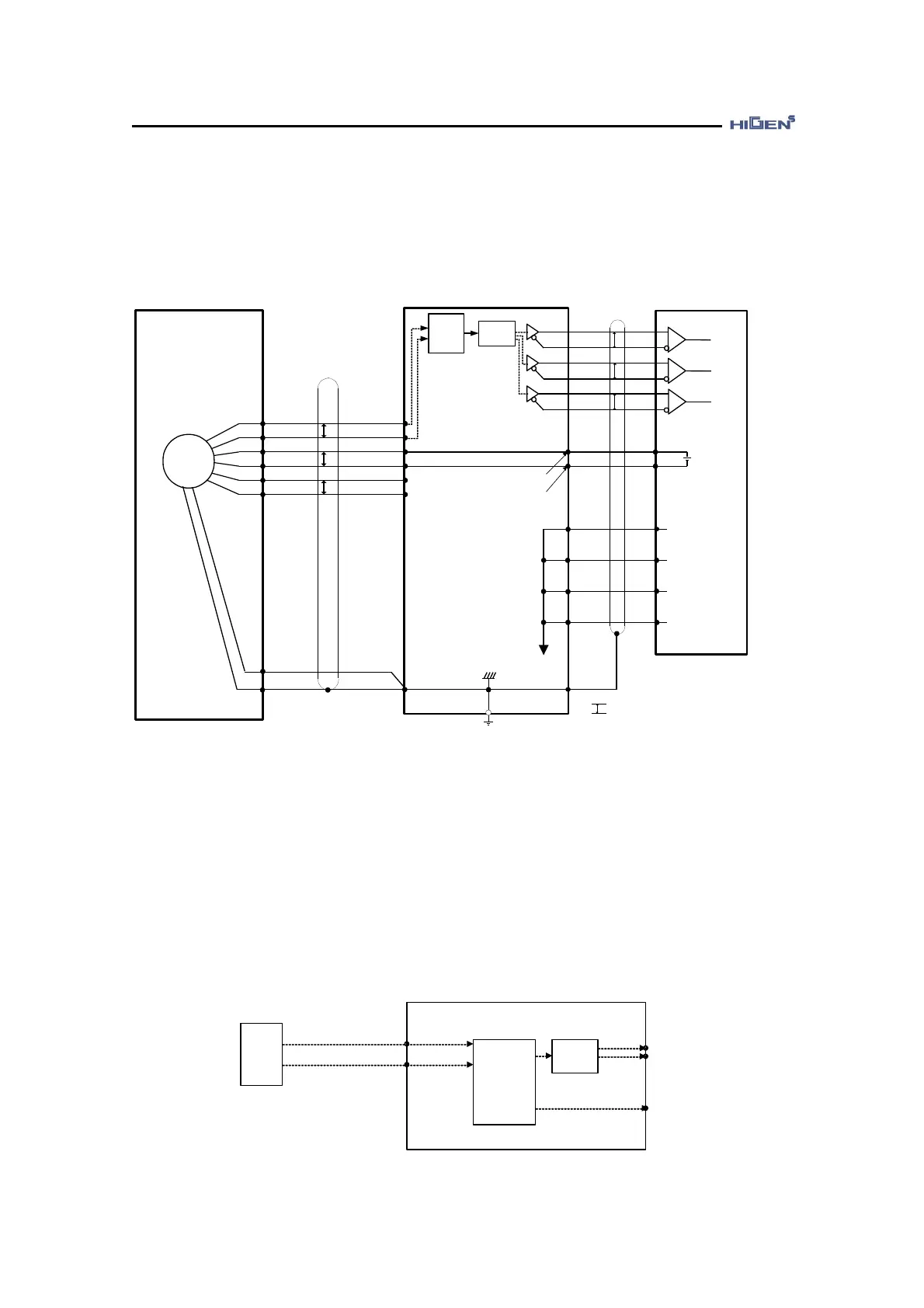
A wiring example of CN2 of motor side (□60,80) and FDA7000(A) when applying the 17bit
absolute/incremental encoder
2-12
EN
2
P
P
P
2-1
2-2
2-7
2-8
2-19
2-9
SD
/SD
BAT+
BAT-
Vcc(5V)
GND(0V)
CN2 CN1 HOST CONTROLLER
1-7
1-32
1-6
1-31
1-5
1-30
AC SERVO DRIVER (FDA7000A)
1-1
1-8
1-33
1-34
0V
PA0
/PA0
PB0
/PB0
PZ0
/PZ0
P
P
P
Used LINE RECEIVER
T.I SN75175
Output LINE DRIVER
T.I SN75174
[*1]
[*1]
[*2]
1-50
[*1] indicates the TWIST PAIR Line.
P
[*2] T.I : TEXAS INSTRUMENT Inc.
1
Division
circuit
Serial
Data
=>
Pulse
Conv.
3
4
5
6
7
+
-
FG
1-29
1-4
AC SERVO MOTOR
(□60,80)
8
Applied cable specification: AWG24 x 9Pair TWIST, SHIELD CABLE (Maximum length 20m)
You do not need to connect the incremental 17bit encoder no. 7 (BT+) and no. 8 (BT-)
terminals,
2.6.5. 17bit absolute encoder data transmission
The output signal of absolute encoder is the incremental division output PAO, /PAO, PBO,
PBO, PZO, /PZO
.
EN
SD
/SD
SERVO DRIVE
Serial Data
->
Pulse Conv.
Division
circuit
(P01-14)
PAO
PBO
PZO