2. Wiring and connection
2-18
2.5. CN1 I/O signal explanation
2.5.1. CN1 terminal arrangement
CN1 is the connector located on the top right part of the front side of the servo drive. This
connector is used for connecting the host controller that commands the operating device and
the operation.
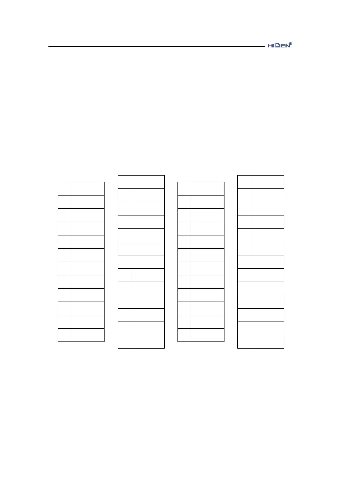
The pin arrangement and name of the CN1 connector are as shown in the following picture.
2 MONIT2
4 OPCRIN
6 PBO
8 GND
10 PFIN
12 PRIN
14
SPDLIM/
TLIM
16 DIR
18 SVONEN
20 ALARM
22
INSPD/INP
OS/INTRQ
24 GND24
1 GND
3 MONIT1
5 PZO
7 PAO
9 PPRIN
11 PPFIN
13 STOP
15
CCWLIM/
PTQLIM
17
SPD2/
GEAR2
19 A_CODE1
21 RDY
23 OPC_ZO
27 SPDIN
29 OPCFIN
31 /PBO
33 GND
35 +12V
37 -12V
39 ESTOP
41 PI/P
43
SPD1/
GEAR1
45 A_CODE0
47 ZSPD
49 +24VIN
26 GND
28 TRQIN
30 /PZO
32 /PAO
34 GND
36 GND
38 ALMRST
40
CWLIM/
NTQLIM
42 SPD3
44 A_CODE2
46
SPDOUT/
TRQOUT
48 BRAKE
25 GND24 50 FG
♥ The above table indicates the reference signal of manufactured default. For the function of
partial pin among the signals, the signal allocation can be changed in P07 mode (input
function setting) and P08 mode (output function setting).
The connector for CN1 is optional.
- Manufacturer: 3M, CASE product name: 10350-52F0-008
- Connector (for soldering) : 10150-3000VE