7. Connection with host controller
7-7
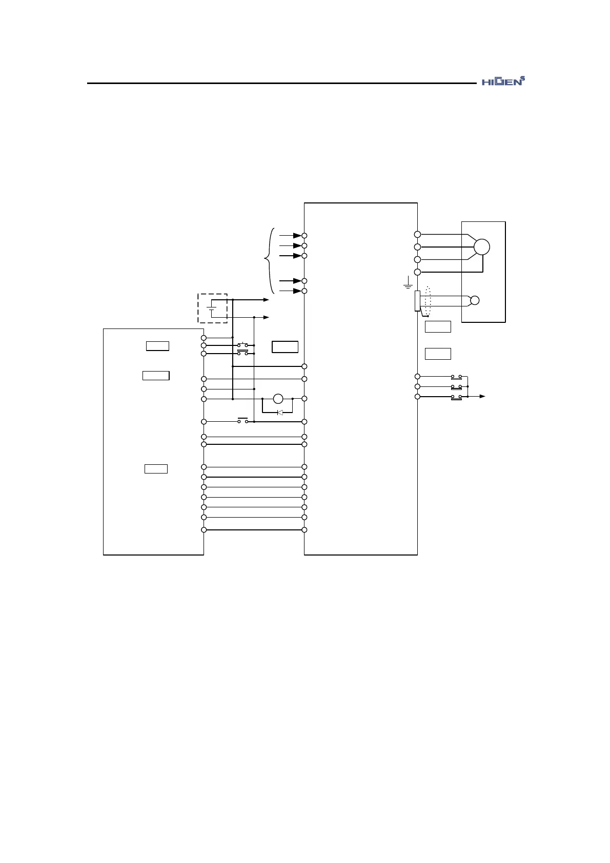
Connection with Electric position decision unit AD72
This is an example of speed control mode servo system operation.
FDA7000
6
5
0V
PULSE A
Analog Velocity
CMD
R
S
T
r
t
GND
GND24V
MITSUBISHI
AD72
M
U
V
W
FG
SERVO MOTOR
PG
CN2
CN1
AC
200 ~ 230V
50/60 Hz
+24V
GND24
+
-
+24V
CN1
49
1
1
READY
STOP
DOG
39
13
17
GND24
CCWLIM/PTQLIM
CWLIM/NTQLIM
ESTOP
24, 25
1Ry
1Ry
ALARM
2
3
CONT
SERVO
ENC0
2
4
SVONEN
3
SPDIN
GND
27
1, 33
+24V
18
SV-ON
PULSE B
4
PULSE C
5
7
8
11
10
3, 6, 9
7
32
6
31
30
5
8
PAO
/PAO
PBO
/PBO
PZO
/PZO
20
(Note) After connecting the power, it takes about 1-2 seconds until the alarm signal leads
to normal operation. Consider this when designing the power connection sequence.
Also the alarm signal operates alarm detection relay 1Ry to turn on the main circuit
power of servo drive.
It only has the signals related to Mitsubishi AD72 and FDA7000 Series
(Note) The above connection is only shown in case of P07-01=26 (Speed control mode).