Do you have a question about the Hikmicro HM-TM36-LG/D and is the answer not in the manual?
Details the technical specifications for the HM-TM36-LG/D thermal camera module.
Details the technical specifications for the HM-TM36-LG/S thermal camera module.
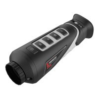
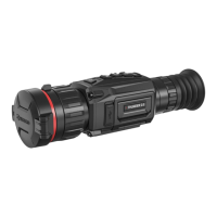
Describes the physical appearance and dimensions of the HM-TM36-LG/D module.
Details the electrical interface description for the 33-pin connector.
Details the electrical interface description for the 4-pin connector.
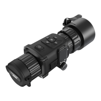
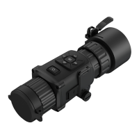
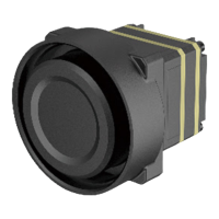
Describes the physical appearance and dimensions of the HM-TM36-LG/S module.
Details the electrical interface description for the 6-pin connector.
Details the electrical interface description for the 12-pin connector.
Details the electrical interface description for the 45-pin connector.
Describes the external cables and their specifications for the thermal camera.
Explains that the module uses UART asynchronous serial communication.
Defines the serial port communication format, including baud rate and data bits.
Details the fields and structure of the data package sent to the module.
Details the fields and structure of the data package received from the module.
Outlines the requirements for serial port communication and command execution.
Lists the serial port commands for controlling the thermal camera module.
Provides examples of serial port command communication.
Details specific commands for controlling thermal module functions.
Command for performing manual shutter correction.
Command for performing manual background correction.
Command to adjust DDE (Digital Detail Enhancement) strength.
Command to adjust the DNR (Digital Noise Reduction) spectral level.
Command to adjust the DNR temporal level.
Command for adjusting the brightness level.
Command for adjusting the contrast level.
Command for Dead Pixel Correction (DPC).
Command for switching between RAW+YUV and BT.656 data output.
Command for controlling the shutter auto-switch function.
Command for manual vignetting correction.
Command to save current settings.
Command to restore default settings.
Command to switch color palettes.
Command for adjusting zoom levels.
Command for adjusting mirror settings (flip/flop).
Command to set the AGC (Automatic Gain Control) mode.
Commands related to menu operations.
Describes the different video data output types from the thermal camera.
Details the LVCMOS digital video output for the HM-TM36-LG/D module.
Describes the BT.656 video output standard and its specifications.
Describes the YUV+RAW video output and its packaging format.
Details the video output options for the HM-TM36-LG/S module.
Describes the OLED micro-display used with the module.
Explains the shortcut key functions for live view adjustments.
Describes the main menu structure and its functions.
Details the submenus accessible from the main menu.
Describes the interface for adjusting reticle parameters.
Describes the interface for Dead Pixel Correction (DPC).
| Pixel Interval | 12 μm |
|---|---|
| Frame Rate | 50 Hz |
| Aperture | F1.0 |
| Hot Spot Mark | Yes |
| Record Video | Yes |
| Capture Snapshot | Yes |
| Wi-Fi | Yes |
| Type-C Interface | Yes |
| Protection Level | IP54 |
| Detector Type | Uncooled VOx Microbolometer |
| Resolution | 384x288 |
| Response Waveband | 8-14μm |
| Palettes | Black hot, white hot, rainbow, ironbow |
| Standby Mode | Auto/Manual |
| Power | 5 VDC/2 A |
| Battery Type | Built-in rechargeable lithium battery |
| Operating Temperature | -20 °C to 50 °C (-4 °F to 122 °F) |
| Spectral Range | 8-14μm |
| Video Output | Yes |
| Battery | Built-in rechargeable lithium battery |
| Storage Temperature | -20 °C to 60 °C (-4 °F to 140 °F) |
| Temperature Measurement Range | -20 °C to 550 °C (-4 °F to 1022 °F) |