EasyManua.ls Logo

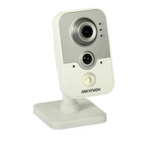
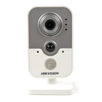
HIKVISION DS-2CD2432F-I

HIKVISION DS-2CD2432F-I
131 pages
To Next Page IconTo Next Page
To Previous Page IconTo Previous Page
Loading...
Installation Manual of Network Camera
36
3.4 Type IV Dome Camera
3.4.1 Camera Description
1
2
3
4
5
6
8
7
Figure 3-33 Overview
Table 3-4 Physical Description
No.
Description
1
Video output interface
2
LINK: Indicator is solid yellow when network is
connected.
3
ACT: Indicator flashes blue when network
connection is functioning properly.
4
PWR: Indicator is solid red when the device is
powered on.
5
Micro SD slot
6
RESET: Reset the camera.
7
10M/100M self-adaptive Ethernet interface
8
Power supply interface
The extended interface can be connected to alarm input/output interface, audio input/output
interface, RS-485 interface, etc.
Lo-Call 1890 866 900
www.cctvireland.ie
shop@cctvireland.ie

Table of Contents

Other manuals for HIKVISION DS-2CD2432F-I

Related product manuals