Concept for HIQuad X System
Page 14 of 110 HI 803 211 E Rev. 1.01.00
3.2 Concept for HIQuad H51X
The H51X system family has a modular structure which includes an H51X base rack and up to
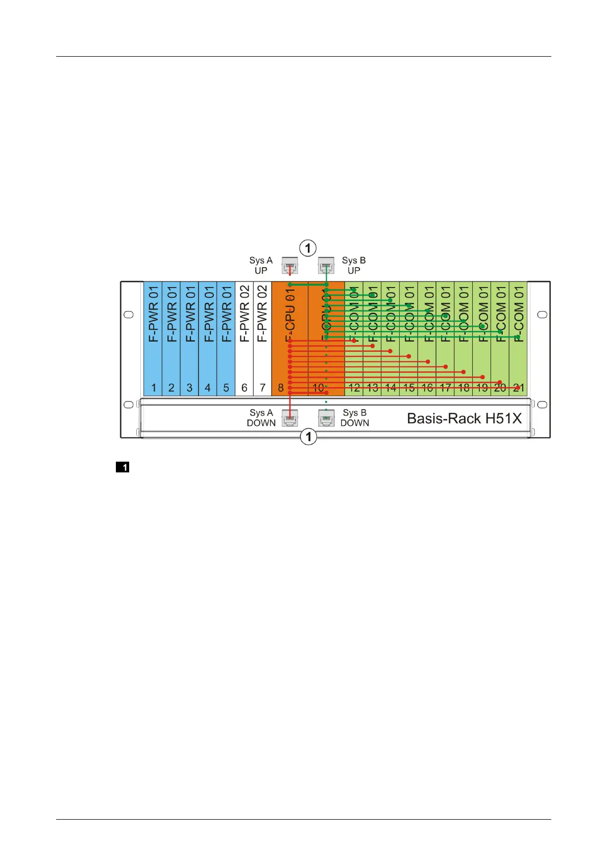
16 extension racks. The H51X base rack (F-BASE RACK 01) can be equipped as shown in
Figure 1.
The communication modules are connected to the processor modules via two system buses (A
and B) in a point-to-point connection. The processor module in slot 8 controls and monitors
system bus A whereas the processor module in slot 10 controls and monitors system bus B.
During redundant operation, the two processor modules align their data.
The RJ-45 interfaces on the rear side of the base rack are used to connect the extension racks
to the processor modules. An I/O processing module (F-IOP 01) must be used in the extension
rack to connect the system buses to the I/O bus, see Figure 2 and Figure 4.
System bus interfaces on the rear side of the base rack
Figure 1: H51X Base Rack Completely Assembled
 Loading...