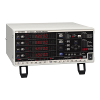
These lamps indicate channel warnings. When the following warning lamps and er-
ror lamps are lit up, they indicate a hazardous state or inability to perform measure-
ment accurately:
PEAK OVER U
Lights up when an overvoltage input warning occurs, indi-
cating that the input voltage peak value has exceeded
±1,500 V or ±600% of the voltage measurement range.
PEAK OVER I
Lights up when an overcurrent input warning occurs, indi-
cating that the input current peak value has exceeded ±100
A or ±600% of the current measurement range.
SYNC. ERROR
Lights up when a synchronization error occurs, indicating
that synchronization cannot be detected.
HRM ERROR
Lights up when a harmonic measurement synchronization
error occurs, indicating that the harmonic measurement
synchronization frequency range was exceeded.
These lamps light up in response to settings on the following setting screens:
CH SET
Channel settings
• Synchronization source
• Current input method
•CT ratio
•VT ratio
• Zero-cross and frequency measurement filter
• Synchronization detection timeout
MEAS. SET
Shared settings that apply to all channels
• Integration time
• Number of averaging iterations
• Harmonic analysis upper limit order
• Synchronized measurement I/O (master, slave)
• D/A output
INTERFACE
Interface settings
• RS-232C
•GP-IB
•LAN

 Loading...