3.2 Configuring Settings
44
This section describes how to select the information shown on the instrument’s display.
• Selecting display parameters
• Selecting display channels
• Selecting rectifiers
See: "Appendix 1 Detailed Specifications of Measurement Items (Display Items)" (p. A1)
Default settings
: Voltage (V), CH1, AC+DC
: Current (A), CH1, AC+DC
: Active power (W), CH1, AC+DC
: Power factor (PF), CH1, AC+DC
Selecting display parameters
This section describes how to select the parameters that are shown on the instrument’s display.
3.2.3 Selecting Display Content
• The voltage and current are displayed from 0.5% to 140% of the range.
(When input is less than 0.5% of the range, zero-suppression forces a value of zero to be displayed.)
• Active power is displayed from 0% to 196% of the range.
(There is no zero-suppression function.)
• Some display parameters do not have measured values depending on the rectifier and wiring mode. In
this case, the display will show [- - - - -].
See:"Appendix 1 Detailed Specifications of Measurement Items (Display Items)" (p. A1)
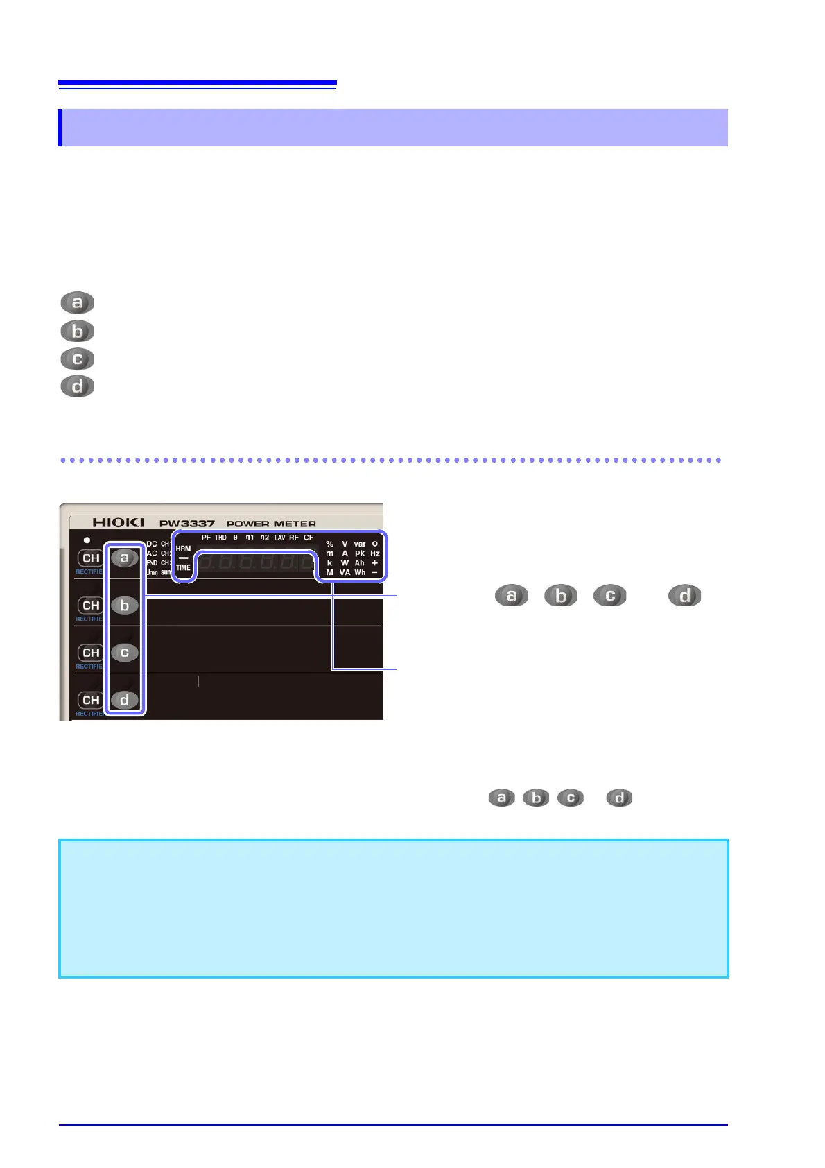
Every time , , , or is
pressed, the each relevant display is
switched in the following order.
V → A → W → VA → Vpk → Apk → VHz → AHz
→ var → Ah+ → Ah- → Ah → Wh+ → Wh- → Wh
→ ° → PF → THD-V → THD-A → θ-V → θ-A → η1
→ η2 → T.AV-A → T.AV-W → RF-V → RF-A → CF-
V
→ CF-A → TIME ⋅⋅⋅
In the shift state, the display parameters cycle through the
values in reverse order. The shift state is canceled approx.
2 seconds after , , , or is released.