3.2 Configuring Settings
43
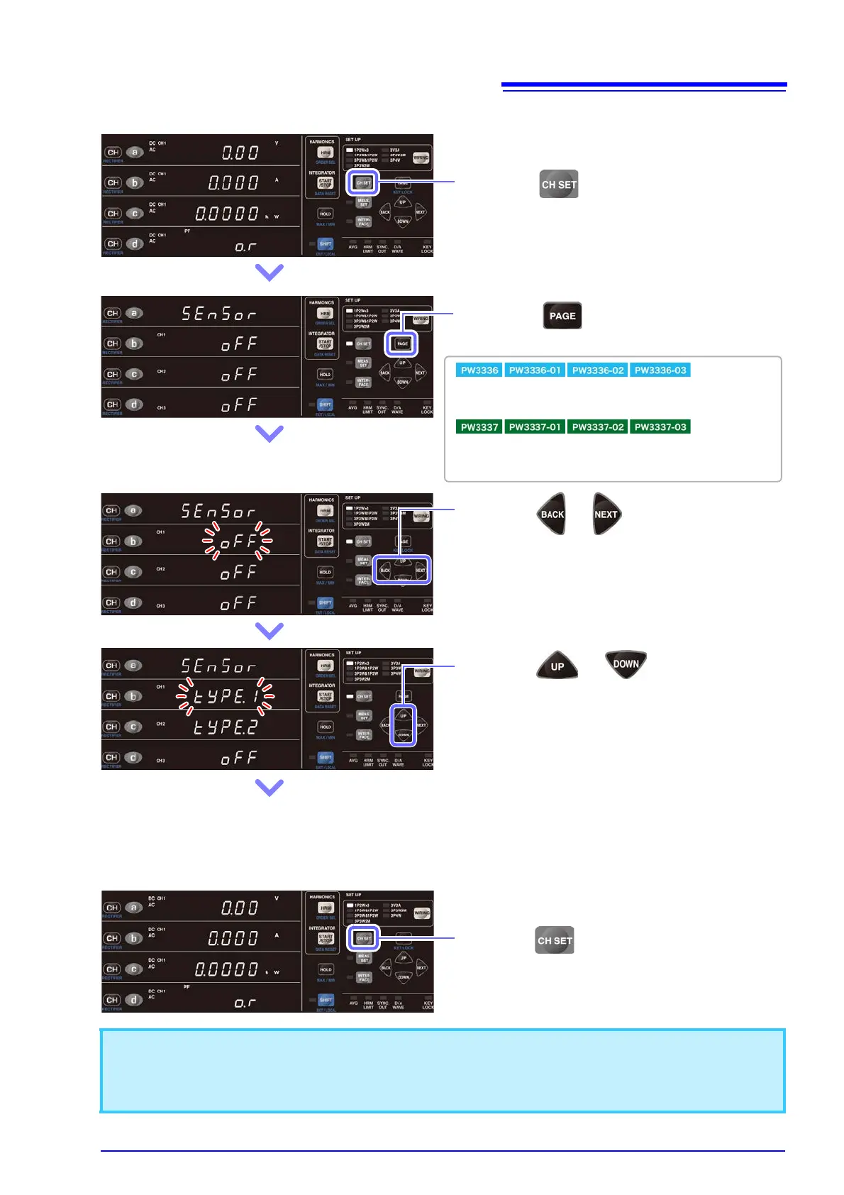
Example: When the PW3337 wiring mode is 1P2W×3
2 Press to display the settings
screen shown to the left.
:
The screen varies depending on whether the wiring mode is
1P2W×2 or a mode other than 1P2W.
:
The screen varies depending on whether the wiring mode is
1P2W×3, 1P3W&1P2W and 3P3W&1P2W, 3P3W2M, or 3V3A
and 3P3W3M and 3P4W.
3 Press or to select the channel
to set.
Areas b, c, and d on the display correspond to CH1, CH2,
and CH3, respectively. The selected channel parameter will
flash.
4 Press or to set the current
input method.
Settings: OFF (direct input) → TYPE1 (BNC
terminal direct connection [using
external sensors]) → TYPE2 (con-
nection via the 9555-10 and L9217
[using external sensors])
(When set to TYPE1 or TYPE2, the EXT.SENSOR lamp for
the set channel will light up.)
5 Set the current input method for other
channels as necessary.
• When using a wiring mode other than 1P2W, the current input method will be standardized using the CH1
settings.
• The current input method cannot be changed while integration is being performed or during display hold or
maximum value/minimum value hold operation.
6 Press to exit the settings.
The instrument will return to the normal measure-
ment state.
 Loading...


