214
Specications of Equations
Wiring
Item
1P2W 1P3W 3P3W2M 3V3A 3P3W3M 3P4W
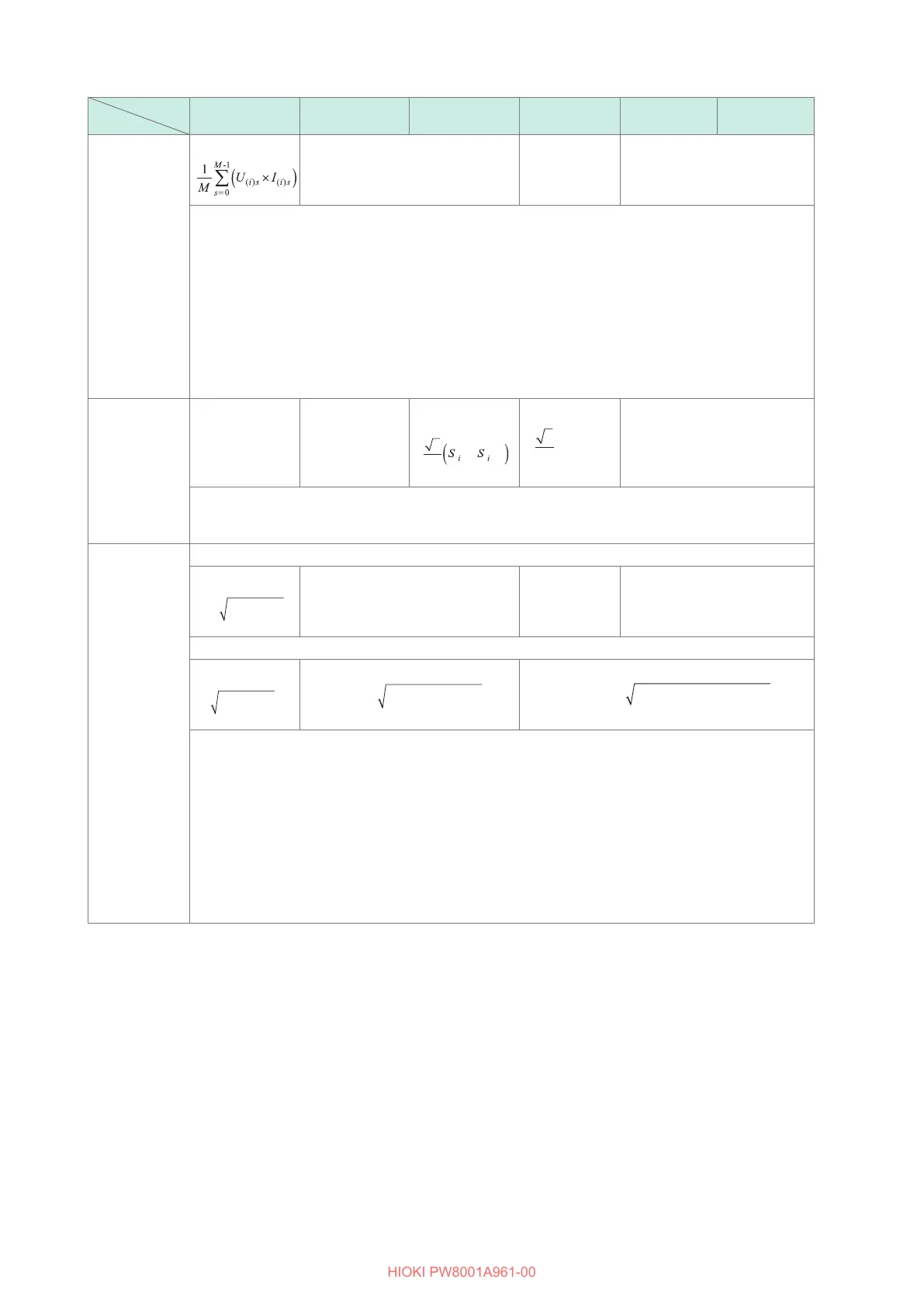
Active power
P
(i)
=
P
(i)(i+1)
= P
(i)
+ P
(i+1)
P
(i)(i+1)(i+2)
= P
(i)
+ P
(i+1)
P
(i)(i+1)(i+2)
= P
(i)
+ P
(i+1)
+ P
(i+2)
• In 3P3W3M and 3P4W wiring modes, voltage waveform
U
(i)s
is phase voltage.
In 3P3W3M wiring mode, sampled voltage, which is line voltage, is converted into phase voltage.
U
(i)s
= (u
(i)s
− u
(i+2)s
) / 3, U
(i+1)s
= (u
(i+1)s
− u
(i)s
) / 3, U
(i+2)s
= (u
(i+2)s
− u
(i+1)s
) / 3
u
(i)s
: sampled line voltage value of channel
(i)
.
U
(i)s
: calculated phase voltage value of channel
(i)
In 3P4W wiring mode, Sampled voltage is phase voltage, which does not need conversion.
• In 3V3A mode with
Δ
-Y conversion set to on, the 3P3W3M or 3P4W equation is used.
• In 3V3A wiring mode, voltage
U
(i)
is line voltage. (3P3W2M and 3V3A wiring modes performs the
same calculation.)
• The polarity sign of active power
P
indicates the owing direction of power:
+P
indicates
consumption, whereas
−P
indicates regeneration.
Apparent
power
S
(i)
= U
(i)
×
I
(i)
S
(i)(i+1)
= S
(i)
+ S
(i+1)
S
(i)(i+1)
S
(i)(i+1)(i+2)
=
(S
(i)
+ S
(i+1)
+ S
(i+2)
)
S
(i)(i+1)(i+2)
= S
(i)
+ S
(i+1)
+ S
(i+2)
• For
U
(i)
and
I
(i)
, the rectication method can be selected between rms and mean.
• In 3P3W3M and 3P4W wiring mode, voltage
U
(i)
is phase voltage.
• In 3V3A mode, voltage
U
(i)
is line voltage.
Reactive power
If equation Type 1 or Type 3 is selected
Q
(i)
=
si
(i)
() ()
−
Q
(i)(i+1)
= Q
(i)
+ Q
(i+1)
Q
(i)(i+1)(i+2)
= Q
(i)
+ Q
(i+1)
Q
(i)(i+1)(i+2)
= Q
(i)
+ Q
(i+1)
+ Q
(i+2)
If equation Type 2 is selected
Q
(i)
=
() ()
−
Q
(i)(i+1)
=
ii ii
()
+
() ()
+
−
1
2
1
2
Q
(i)(i+1)(i+2)
=
PS
(i)(i+1)(i+2) (i)(i+1)(i+2)
2 2
−
• If equation Type 1 or Type 3 is selected, the polarity sign
si
for the reactive power
Q
indicates the
lead/lag polarity; no sign indicates lag, whereas a negative sign (−) indicates lead.
• The polarity sign
si
(i)
is acquired based on the lead/lag between voltage waveform
U
(i)s
and current
waveform
I
(i)s
for each measurement channel
(i)
.
• In 3P3W3M and 3P4W wiring modes, voltage waveform
U
(i)s
is phase voltage.
In 3P3W3M wiring mode, sampled voltage, which is line voltage, is converted into phase voltage.
U
(i)s
= (u
(i)s
− u
(i+2)s
) / 3, U
(i+1)s
= (u
(i+1)s
− u
(i)s
) / 3, U
(i+2)s
= (u
(i+2)s
− u
(i+1)s
) / 3
u
(i)s
: sampled line voltage value of channel
(i)
.
U
(i)s
: calculated phase voltage of channel
(i)
• In 3P4W wiring mode: Sampled voltage, which is phase voltage, does not need conversion.
• If equation Type 2 is selected, results are unsigned.
 Loading...


