88
Motor Measurement (Motor Analysis-Equipped Model)
Setting rotation signal input
Setting items of RPM signal input varies depending on the pattern of the motor analysis mode
connection.
Analog For a DC voltage signal proportional to the RPM
Pulse For a pulse signal proportional to the RPM
The setting items vary depending on the setting.
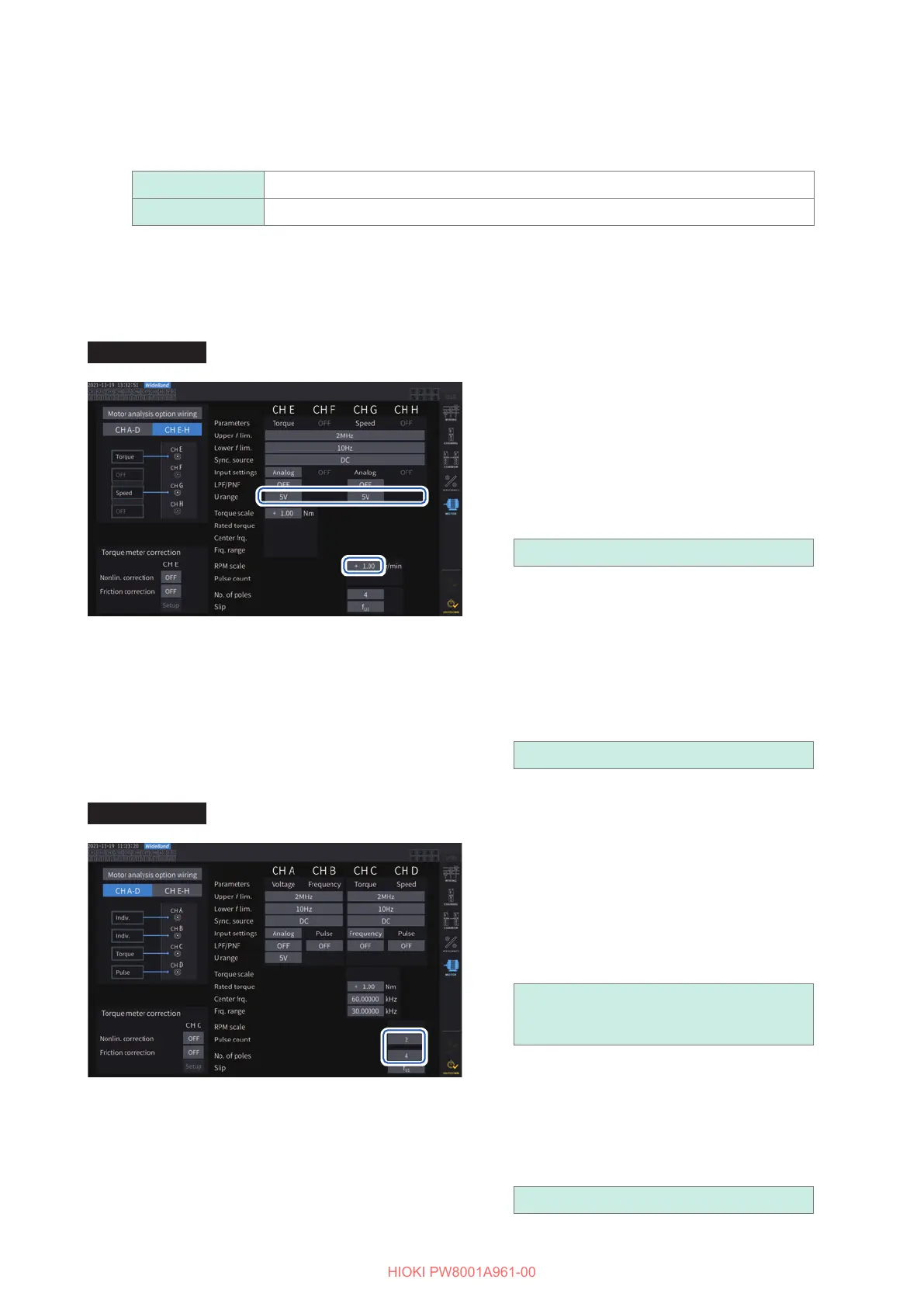
When the input setting is set to [Analog]
Congure the voltage range and RPM scaling settings based on the rotation signal.
Display screen [INPUT] > [MOTOR]
[U range]
Select a voltage range according to the output
voltage of the rotation signal inputted to the
instrument.
The voltage range of the rotation signal input
can also be set using the current range keys
while the [A-D] or [E-H] channel indicator is lit
up.
1 V, 5 V, 10 V
[RPM scale]
Enter the RPM scale using the numeric keypad
window.
The result of multiplying the input voltage by
the scaling value is displayed as the measured
RPM value.
Enter the RPM per volt of the rotation signal
output.
±
0.00001 to 99999.9
When the input setting is set to [Pulse]
Display screen [INPUT] > [MOTOR]
[Pulse count]
If an incremental-type rotary encoder with 1000
pulses per rotation is connected, enter 1000.
You can use the numeric keypad window.
Specifying this parameter with a multiple of half
of the motor’s pole number setting will enable
to select Ext as the synchronization source.
±
1 to 60000
(number of pulses per mechanical angle
rotation)
[No. of poles]
This value is used to perform slip calculation
as well as convert the RPM signal into a
frequency corresponding to the electrical
angle.
You can use the numeric keypad window.
2 to 254 (even number)
 Loading...


