Installation BAT
Release
05
03/2013
59
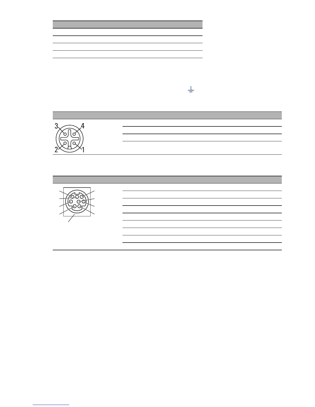
The connector is a 4-pin M12 female connector with A coding.
On delivery, the connector is sealed with a cover cap.
The housing of the M12 socket and the signal connectors are electrically
connected to the functional ground (FE) ( ) and to the metal housing of
the device.
Note: You will find the order number for the terminal cable, which is
ordered separately, in the ”Technical Data” chapter (see on page 62
“Technical data”).
VT 100 terminal settings
Data 8 bit
Stopbit 1 bit
Handshake off
Parity none
Figure Pin Function
1 TX Transmit data
2 RX Receive data
3 N.C. Not connected
4 GND Ground
Table 10: Pin assignment of the V.24 interface for BAT-F (M12 socket)
Figure Pin Function
1 CTS Clear to send
2 RTS Request to send
3 RxD Receive data
4 RI Ring indicator
5 TxD Transmit data
6 DSR Dataset ready
7 DCD Data carrier detect
8 DTR Data terminal ready
U GND Ground
Table 11: Pin assignment of the V.24 interface for BAT-Rail (miniDin socket)
1
6
3
4
2
8
5
7
U