I English
OPTIONAL ACCESSORIES...sold separately
[1] ExtensionHolderand Stopper(CodeNo.322710)
42) Saw blade 10" (255mm)TCT Saw blade for wood cut (Totalteeth:
60) (CodeNo.976472)
[3) Sawblade10"(255mm)TCTSawbladefor aluminum cut (Totalteeth:
100)(CodeNo.319658)
[4_ Crown molding Vise Ass'y (Code No. 322712) (Include Crown
molding Stopper(L))
[5) Crown molding Stopper(L)(CodeNo. 322713)
[6) Crown molding Stopper(R)(CodeNo. 322714)
NOTE:
Accessoriesaresubjectto changewithout any obligationonthe
partof theHITACHI.
APPLICATIONS
Woodand aluminum sash.
PREPARATION BEFORE OPERATION
Make the following preparations before operating the power tool:
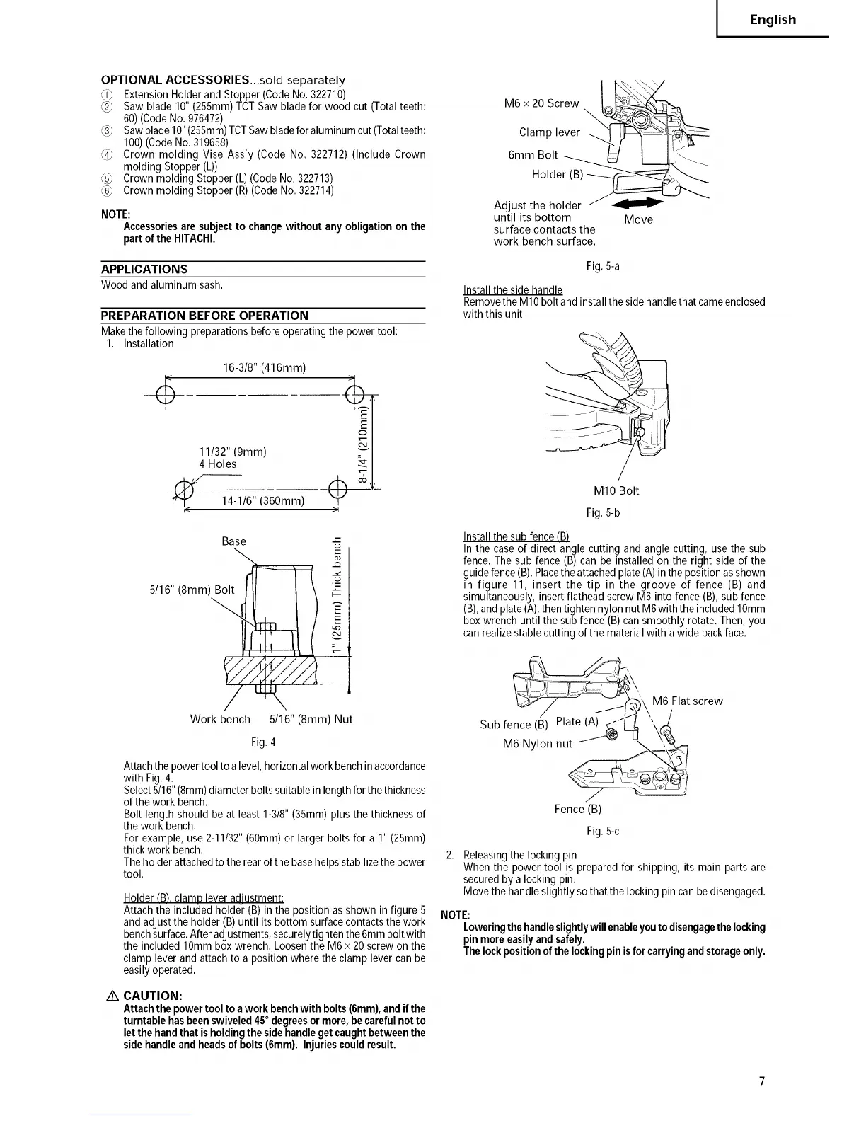
1. Installation
16-3/8" (416mm)
11/32" (9mm)
4 Holes
_ 14-1/6" (360mm)
.)
)1
Base -=
{3
5/16" (8ram) Bol
E
Work bench 5/16" (8ram) Nut
Fig.4
Attach the power tool to a level, horizontal work bench in accordance
with Fig. 4.
Select 5/16" (8mm) diameter bolts suitable in length for the thickness
of the work bench.
Bolt length should be at least 1-3/8" (35mm) plus the thickness of
the work bench.
For example, use 2-11/32" (60ram) or larger bolts for a 1" (25ram)
thick work bench.
The holder attached to the rear of the base helps stabilize the power
tool.
Holder (B),clamp lever adjustment:
Attachthe includedholder (B)in the position as shown in figure 5
and adjustthe holder (B) until its bottom surfacecontactsthe work
benchsurface.Afteradjustments,securelytighten the6mmboltwith
the included 10mmbox wrench. Loosenthe M6 x 20screw on the
clamp lever and attachto a position where the clamp lever canbe
easilyoperated.
/_ CAUTION:
Attachthepowertooltoa workbenchwith bolts(6mm),andifthe
turntablehasbeenswiveled45° degreesormore,becarefulnotto
letthehandthatisholdingthesidehandlegetcaughtbetweenthe
sidehandleandheadsof bolts(6mm). InJuriescouldresult.
M6x2OScrew _ ___
Adjust tiilii[__
until its bottom Move
surface contacts the
work bench surface.
Fig.5-a
Install the side handle
Remove the MIO bolt and install the side handle that came enclosed
with this unit.
MIO Bolt
Fig.5-b
Installthe sub fence(B)
In the caseof direct angle cutting and angle cutting, use the sub
fence.The sub fence (B) can be installed on the right side of the
guide fence(B).Placetheattachedplate (A)in theposition asshown
in figure 11, insert the tip in the groove of fence (B) and
simultaneously, insert flathead screwM6 into fence(B),subfence
(B),and plate(A),thentighten nylon nutM6with the included10mm
box wrench until the subfence (B) cansmoothly rotate.Then, you
canrealizestablecutting of the materialwith a wide backface.
_\M6 Flat screw
Sub fence (_ Plate (A_J_'\'\ ,.-_
M6 Nylon nut_,j_
Fence (B)
Fig.5-c
Releasingthe locking pin
Whenthe powertool is preparedfor shipping, its main parts are
securedby a lockingpin.
Move the handleslightly so that the lockingpin canbedisengaged.
NOTE:
Loweringthehandleslightlywillenableyoutodisengagethelocking
pinmoreeasilyandsafely.
Thelockpositionofthelockingpinisfor carryingandstorageonly.