English I
Handle
9
Locking pin
Fig. 6
Installing the dust bag, holder,stopper and vises
(Theholder and stopper are optional accessories.)
Attachthe dust bagandviseassemblyas indicatedin Fig.1and Fig.
2.
BEFORE USING
1. Makesure the power source isappropriatefor the tool.
/k
WARNING:
NeverconnectthepowertoolunlesstheavailableACpowersource
isof the samevoltageasthat specifiedon the nameplateof the
tool.
Neverconnectthispowertoolto a DCpowersource.
2. Makesure the trigger switch isturned OFF.
/k
WARNING:
Ifthepowercordisconnectedto thepowersourcewith thetrigger
switchturnedONthepowertool willstartsuddenlyandcancause
a seriousaccident.
3. Checkthe saw bladefor visible defects.
Confirmthat thesaw bladeisfreeof cracksor othervisible damage.
4. Confirmthat the saw blade is attachedsecurelyto the powertool.
Using the supplied 10mm boxwrench,tighten the bolt on the saw
blade spindleto securethe saw blade.
For details, see Fig. 33-a, Fig. 33-b, Fig. 33-c and Fig. 33-d in the
sectionon "SAW BLADEMOUNTINGANDDISMOUNTING".
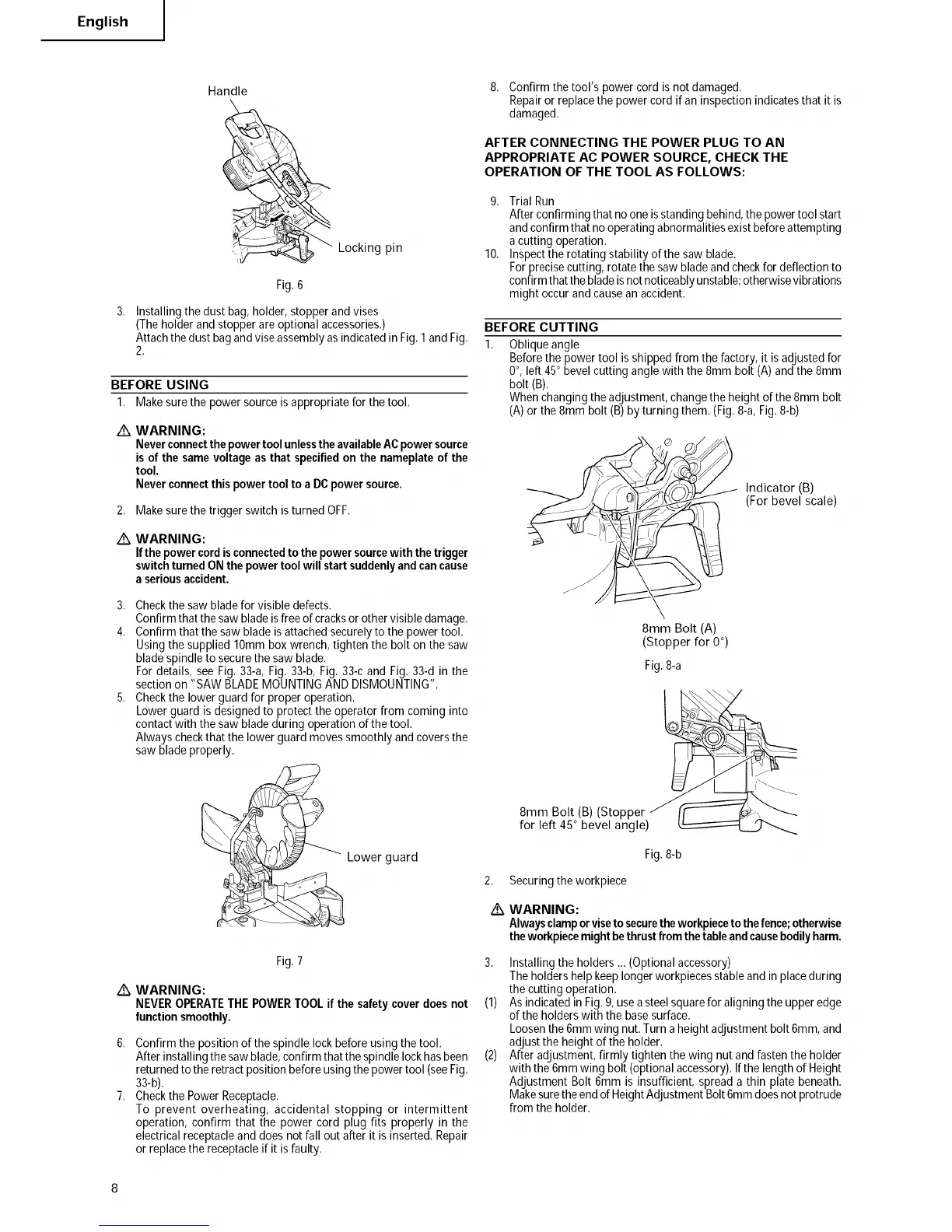
5. Checkthe lowerguard for proper operation.
Lowerguard is designedto protect the operator from coming into
contactwith the saw bladeduring operation of the tool.
Always checkthat the lower guardmovessmoothly and coversthe
saw blade properly.
Lower guard
./k
Fig.7
WARNING:
NEVEROPERATETHEPOWERTOOLifthe safetycoverdoesnot
function smoothly.
6. Confirmthe position of the spindle lockbefore using thetool.
After installingthe sawblade,confirm that thespindle lockhasbeen
returnedto the retractposition before usingthe powertool (seeFig.
33-b).
7. Checkthe PowerReceptacle.
To prevent overheating, accidental stopping or intermittent
operation, confirm that the power cord plug fits properly in the
electricalreceptacleand does notfall out after it is inserted. Repair
or replacethe receptacleif it isfaulty.
8. Confirmthe tool's powercord is not damaged.
Repairor replacethe powercord if aninspection indicatesthat it is
damaged.
AFTER CONNECTING THE POWER PLUG TO AN
APPROPRIATE AC POWER SOURCE, CHECK THE
OPERATION OF THE TOOL AS FOLLOWS:
9. Trial Run
Afterconfirming that noone isstanding behind,the power tool start
andconfirm that nooperatingabnormalitiesexist beforeattempting
a cutting operation.
10. Inspectthe rotating stability of the saw blade.
Forprecisecutting, rotatethe saw bladeand checkfor deflection to
confirmthatthebladeis notnoticeablyunstable;otherwisevibrations
might occur and causean accident.
BEFORE CUTTING
1. Oblique angle
Beforethe power tool is shippedfrom the factory, it isadjustedfor
0°, left 45° bevel cuttingangle with the 8mm bolt (A) and the 8mm
bolt (B).
Whenchangingthe adjustment,changethe heightof the 8ram bolt
(A)or the 8mm bolt (B)by turning them. (Fig.8-a, Fig.8-b)
Indicator (B)
(For bevel scale)
8mm Bolt (A)
(Stopper for 0°)
Fig.8-a
2,
/k
8mm Bolt (B) (Stopper
for left 45° bevel angle)
Fig.8-b
Securingthe workpiece
WARNING:
Alwaysclamporvisetosecurethe workpieceto thefence;otherwise
theworkpiecemightbethrustfromthetableandcausebodilyharm.
3. Installing the holders ... (Optionalaccessory)
Theholdershelpkeeplonger workpiecesstableand in placeduring
the cutting operation.
(1) As indicatedin Fig.9,usea steelsquarefor aligningtheupper edge
of the holderswith the basesurface.
Loosenthe 6ramwing nut.Turn a heightadjustmentbolt 6ram,and
adjustthe heightof the holder.
(2) After adjustment,firmly tighten the wing nut and fasten the holder
with the 6ramwing bolt (optionalaccessory).If the lengthof Height
Adjustment Bolt 6mm is insufficient,spread a thin plate beneath.
Makesurethe endofHeightAdjustmentBolt6ramdoesnot protrude
from the holder.