English I
(1)
(2)
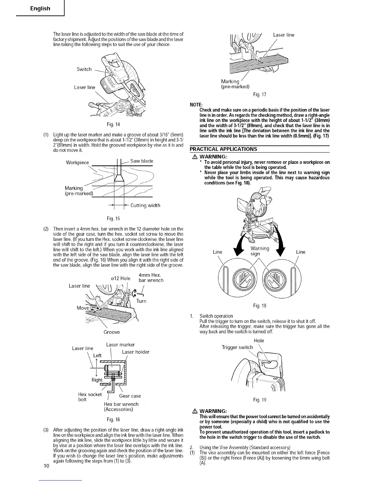
The laser line is adjusted to the width of the saw blade at the time of
factory shipment. Adjust the positions of the saw blade and the laser
line taking the following steps to suit the use of your choice,
Switch _-_ _ _X
Laser line __
Fig.14
Light up the lasermarkerand makea groove of about 3/16"(5mm)
deeponthe workpiecethat isabout 1-1/2"(38mm)in heightand3-1/
2"(89mm)inwidth. Holdthe groovedworkpiece by viseas it isand
do not move it.
Workpiece
Saw blade
Marking
(pre-marked)
Cutting width
Fig.15
Theninsert a 4mm hex.bar wrench in the 12diameter hole on the
side of the gearcase,turn the hex. socketset screwto move the
laserline. (Ifyou turn the Hex.socketscrewclockwise,the laserline
will shift to the right and if you turn it counterclockwise,the laser
line will shift to the left.) When you work with the ink line aligned
with the left sideof the saw blade, align the laserline with the left
end ofthe groove. (Fig.16)Whenyou align it with the right side of
the saw blade,align the laser linewith the right sideof the groove.
4mm Hex.
o12 Hole bar wrench
Laser line _ _ , _>
K^
IvIo
h
Groove
Laser marker
Laser line
Laser holder
!,::J_ _JU_)/ Laser line
Marking
(pre-marked)
Fig.17
NOTE:
Checkandmakesureona periodicbasisif the positionofthe laser
lineisinorder.Asregardsthecheckingmethod,draw aright-angle
ink lineonthe workpiecewith theheightof about1-1/2" (38mm)
andthewidthof 3-1/2"(89mm),andcheckthatthe laserlineisin
linewith the ink line[Thedeviationbetweenthe inklineandthe
laserlineshouldbe lessthanthe inklinewidth(0.Smm)].(Fig.17)
PRACTICAL APPLICATIONS
Z_ WARNING:
* Toavoidpersonalinjury,neverremoveorplacea workpieceon
the tablewhilethetool isbeingoperated.
* Never placeyour limbsinsideof the line nextto warningsign
while the tool is being operated.This may causehazardous
conditions(seeFig.18).
Line Warning
sign Line
Fig.18
Switch operation
Pull thetrigger to turn on the switch,releaseit toshut it off.
After releasingthe trigger, make sure the trigger has goneall the
way backandthe switch isturned off.
Hole
Trigger switch
(3)
lO
i
Right
Hex socket Gear case
bolt
Hex bar wrench
(Accessories)
Fig.16
After adjustingthe position of the laser line, draw a right-angle ink
line onthe workpieceandalign the inkline with the laserline. When
aligning the ink line, slide the workpiecelittle by little and secureit
by vise ata position wherethe laserline overlapswith the ink line.
Workonthe groovingagain andcheckthe positionof the laser line.
If you wish to changethe laser line's position, make adjustments
again following thestepsfrom (1)to (3).
/k
2,
(1)
Fig.19
WARNING:
Thiswillensurethatthepowertoolcannotbeturnedonaccidentally
or bysomeone(especiallyachild)who is not qualifiedto usethe
powertool.
Topreventunauthorizedoperationof thistool,inserta padlockto
theholeinthe switchtriggerto disabletheuseoftheswitch.
Using the ViseAssembly(Standardaccessory)
Thevise assembly can bemounted on either the left fence{Fence
(B)}or the right fence {Fence(A)}by looseningthe 6mmwing bolt
(A).