I English
(2)
(3)
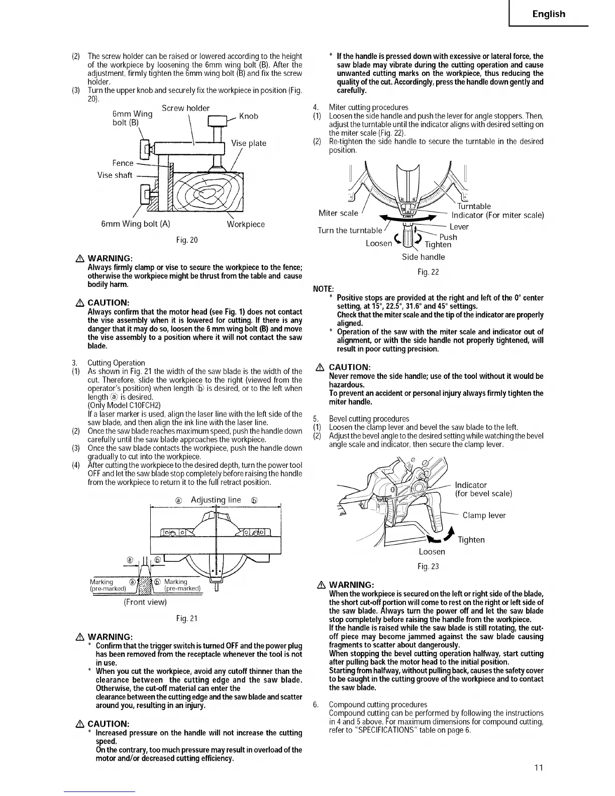
Thescrewholder canbe raisedor lowered accordingto the height
of the workpiece by loosening the 6mm wing bolt (B). After the
adjustment,firmly tighten the 6mm wing bolt (B)andfix the screw
holder.
Turnthe upper knoband securelyfix the workpiecein position (Fig.
20),
Screw holder
6mm Wing _ _ _ Knob
bolt (B) \ I.,_.! f
Viseg:#:f_ _ ise plate
/ "\
6mm Wing bolt (A) Workpiece
Fig.20
Z_ WARNING:
Alwaysfirmly clamporviseto securetheworkpieceto thefence;
otherwisetheworkpiecemightbethrustfrom thetableand cause
bodilyharm.
Z_ CAUTION:
Alwaysconfirmthatthe motorhead (seeFig. 1)doesnot contact
the viseassemblywhen it is loweredfor cutting.If there is any
dangerthat itmaydoso,loosenthe6 mmwing bolt(B)andmove
theviseassemblyto a positionwhereit will not contactthe saw
blade.
3. Cutting Operation
(1) As shown in Fig.21the width of the saw blade is the width of the
cut. Therefore, slidethe workpiece to the right (viewed from the
operator's position) when length @ is desired, or to the left when
length_ is desired.
(OnlyModel C10FCH2)
If a lasermarkeris used, alignthe laser line with the leftside of the
saw blade,and then align the ink linewith the laser line.
(2) Oncethesawbladereachesmaximumspeed,pushthehandledown
carefullyuntil the saw bladeapproachesthe workpiece.
(3) Oncethe saw blade contactsthe workpiece,pushthe handledown
gradually to cut into the workpiece.
(4) Aftercutting theworkpieceto the desireddepth,turn the powertool
OFFand letthe sawbladestop completelybeforeraising the handle
from the workpieceto return it to thefull retract position.
® Adjusti
Marking ® @ Marking
(pre-_arked) ®_:_ (pre-_arked)
(Front view)
ng line ®
Fig.21
Z_ WARNING:
* Confirmthat thetriggerswitchisturnedOFFandthepowerplug
hasbeenremovedfrom thereceptaclewheneverthetool isnot
in use.
* Whenyou cuttheworkpiece,avoidanycutoffthinnerthanthe
clearance between the cutting edge and the saw blade.
Otherwise,thecut-offmaterialcanenterthe
clearancebetweenthecuttingedgeandthesawbladeandscatter
aroundyou, resultingin an injury.
Z_ CAUTION:
* Increasedpressureon the handlewill not increasethe cutting
speed.
Onthecontrary,toomuchpressuremayresultinoverloadofthe
motorand/or decreasedcuttingefficiency.
* Ifthe handleis presseddownwith excessiveorlateral force,the
sawblademay vibrateduringthe cuttingoperationandcause
unwantedcutting markson the workpiece,thus reducingthe
qualityofthecut.Accordingly,pressthehandledowngentlyand
carefully.
4. Miter cutting procedures
(1) Loosenthe side handleand pushthe leverfor anglestoppers.Then,
adjusttheturntable until the indicatoralignswith desiredsetting on
the miter scale(Fig.22).
(2) Re-tightenthe side handle to securethe turntable in the desired
position.
]urntable
Miter scale Indicator (For miter scale)
Turn the turntable
Lever
I'/ ill_ _Push
Loosen "_ Tighten
Side handle
Fig. 22
NOTE:
* Positivestopsareprovidedat the rightandleft of the 0° center
setting,at 15°, 22.5°, 31.6° and450settings.
Checkthatthemiterscaleandthetip oftheindicatorareproperly
aligned.
* Operationof the saw with the miter scaleandindicatorout of
alignment,orwith thesidehandlenot properlytightened,will
resultin poorcuttingprecision.
/k CAUTION:
Neverremovethe sidehandle;useofthetoolwithout it would be
hazardous.
Topreventanaccidentorpersonalinjuryalwaysfirmly tightenthe
miterhandle.
5. Bevelcutting procedures
(1) Loosenthe clamp leverand bevelthe saw bladeto the left.
(2) Adjustthebevelangleto the desiredsettingwhilewatchingthe bevel
angle scaleand indicator,then securethe clamp lever.
I(fn°d_cbal°ri scale)
_ Clamp lever
__P_ Tighten
Loosen
Fig.23
/k
WARNING:
Whentheworkpieceissecuredontheleftorrightsideofthe blade,
theshortcut-offportionwillcometo restontherightorleftsideof
the saw blade.Alwaysturn the poweroff and let the saw blade
stopcompletelybeforeraisingthe handlefrom theworkpiece.
Ifthe handleis raisedwhilethe saw bladeisstill rotating,the cut-
off piecemay becomejammed againstthe saw blade causing
fragments to scatteraboutdangerously.
Whenstoppingthe bevelcuttingoperationhalfway,startcutting
afterpullingbackthe motorheadto theinitialposition.
Starting from halfway,withoutpullingback,causesthesafetycover
to becaughtinthecuttinggrooveof theworkpieceandto contact
thesaw blade.
Compoundcutting procedures
Compoundcutting canbe performed by following the instructions
in 4and 5 above.Formaximum dimensions for compound cutting,
refer to "SPECIFICATIONS"table on page6.
11