English I
CAUTION:
Alwayssecuretheworkpiecewiththerighthandsidefor compound
cutting.Neverrotatethe tableto the rightfor compoundcutting,
becausethe sawblademight thencontactthe clamporvisethat
securestheworkpiece,andcausepersonalinjuryordamage.
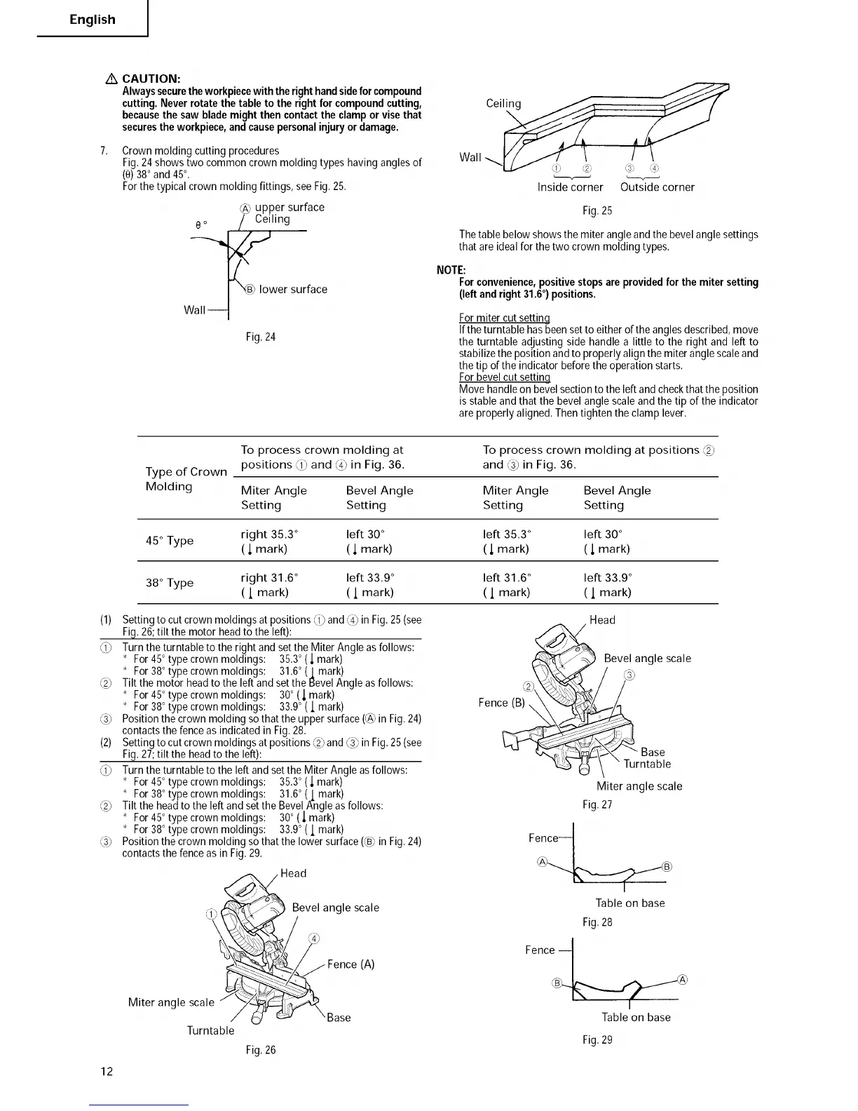
Crown molding cutting procedures
Fig.24 showstwo common crown molding types having angles of
(O)380and 45°.
Forthe typicalcrown molding fittings, seeFig. 25.
@ upper surface
e o / Ceiling
lower surface
Wall---1
Fig.24
Wall
Inside corner Outside corner
Fig.25
Thetable below showsthe miter angleand the bevelangle settings
that are idealfor thetwo crown molding types,
NOTE:
Forconvenience,positivestopsareprovidedfor themiter setting
(leftandright31.60) positions.
For miter cut setting
If the turntable has been set to either of the angles described, move
the turntable adjusting side handle a little to the right and left to
stabilize the position and to properly align the miter angle scale and
the tip of the indicator before the operation starts.
For bevel cut setting
Move handle on bevel section to the left and check that the position
is stable and that the bevel angle scale and the tip of the indicator
are properly aligned. Then tighten the clamp lever.
(1) Settingto cut crown moldingsat positions _1_and _4_in Fig.25(see
Fig.26;tilt the motor headto the left):
_1_ Turn the turntableto the right and set the Miter Angle asfollows:
* For45°type crown moldings: 35.3° (l mark)
* For38°type crown moldings: 31.6°(1 mark)
_2_ Tilt the motor headto the left andset the BevelAngle asfollows:
* For45°type crown moldings: 30° (_ mark)
* For38°type crown moldings: 33.9° (l mark)
_3_ Positionthe crown molding so that the uppersurface(@ in Fig.24)
contactsthe fenceasindicated in Fig.28.
(2) Settingto cut crown moldingsat positions _2_and_3_in Fig,25(see
Fig.27;tilt the headto the left):
_1_ Turn the turntableto the left and setthe MiterAngle asfollows:
* For45°type crown moldings: 35.30(l mark)
* For38°type crown moldings: 31.6° (l mark)
_2_ Tilt the headto the left andset the BevelA-ngleas follows:
* For45°type crown moldings: 30° (l mark)
* For38°type crown moldings: 33.9°(l mark)
_3_ Positionthe crown molding so that the lower surface(@ in Fig.24)
contactsthe fenceasin Fig.29.
To process crown molding at To process crown molding at positions _2_
Type of Crown positions _1_and _4_in Fig. 36. and _3_in Fig. 36.
Molding Miter Angle Bevel Angle Miter Angle Bevel Angle
Setting Setting Setting Setting
45 ° Type right 35.3 ° left 30 ° left 35.3 ° left 30 °
( _,mark) ( l mark) ( _,mark) ( l mark)
38 ° Type right 31.6 ° left 33.9 ° left 31.6 ° left 33.9 °
( I mark) ( 1 mark) ( l mark) ( I mark)
Head
12
Miter angle scale "_
/
Turntable
Head
Bevel angle scale
_:__..///Fence (A)
_Base
Fig.26
Fence (B) \
Bevel angle scale
_Base
" Turntable
Miter angle scale
Fig.27
Fence t
Table on base
Fig.28
Fence --I
Table on base
Fig.29