APCQ CAPACITOR BANKS
© 2022 Hitachi Energy. All rights reserved
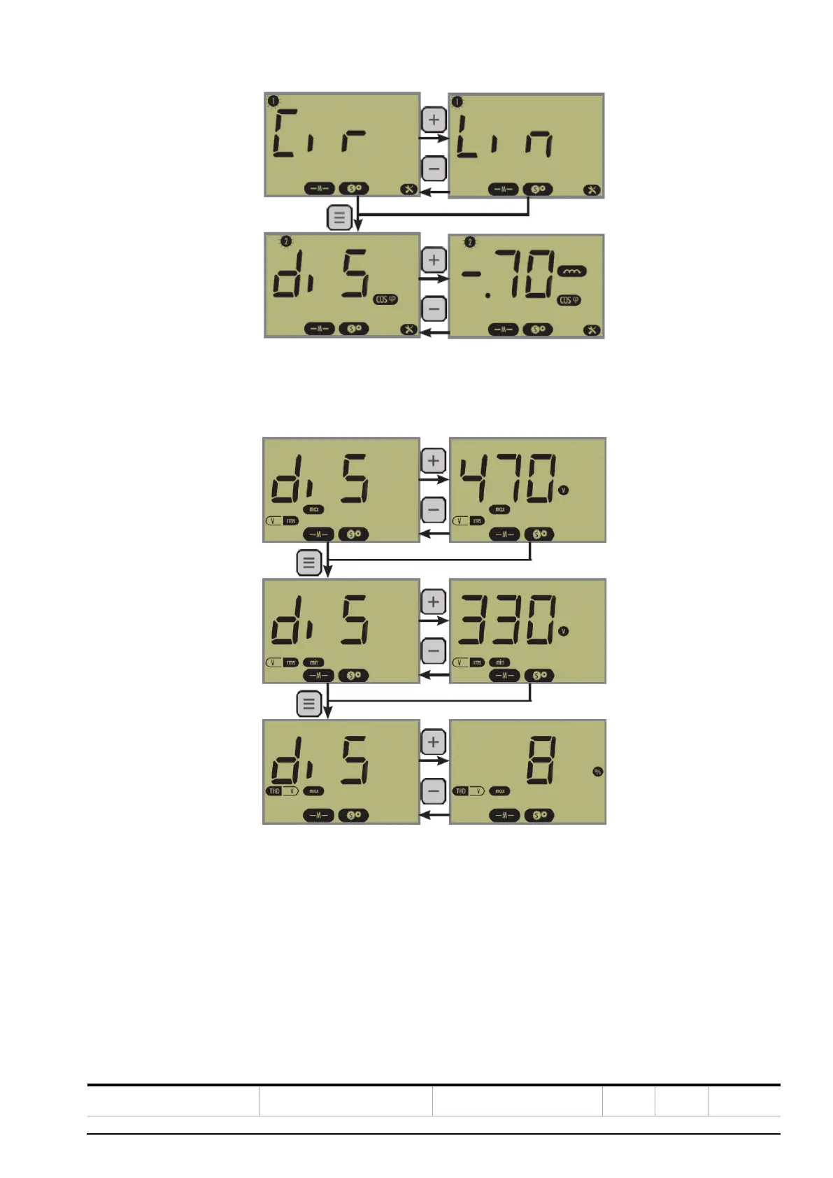
Figure 48: View of the “Feature” parameters
Finally, set the protections: Protection 1 (overvoltage - Max Vrms), Protection 2 (undervoltage - Min Vrms) and Protec-
tion 3 (over THDV - Max THDV).
Figure 42 View of the Protections parameters
Once back in AUTO Mode, the RVC automatically switches on the necessary steps to reach the programmed target
cos ϕ.
The actual cos ϕ appears on the LCD display.
Note: a negative cos ϕ indicates that the load is re-injecting reactive power on the network. The RVC continues to
work normally.
For RVT, please refer to RVT manual provided within the capacitor bank.