3 - 1
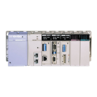
Chapter 3 Name and function of each part
Name and function of each part
When dismounting the module from a base unit, press
this button and lift up the module.
The module can be fixed firmly by a screw (M4, 10 mm
(0.39 in.)).
This LED displays the status of module.
Resets when the module is abnormal.
Used to connect the RS-232C I/F.
Selection with
Communication
Setting Switch
Used to connect the RS-422 I/F or RS-485 I/F.
Used to connect the RS-232C I/F.
Selection with
Communication
Setting Switch
Used to connect the RS-422 I/F or RS-485 I/F.
Communication setting switch
The communication specification is configured by this
switch.
Please set according to connected devices after the power
off and dismounting from a base unit.
* Communication interface of Port 1 is selectable in hardware Rev. 10 or newer. The hardware before Rev. 10 supports
RS-232C only.
[4] Connector for Port1
(RS-232C or RS-422/485)
[5] Connector for Port2
(RS-232C)
[6] Connector for Port2
(RS-422/485)
[7] Communication setting switch

 Loading...