EQUIPMENT DESCRIPTION
4
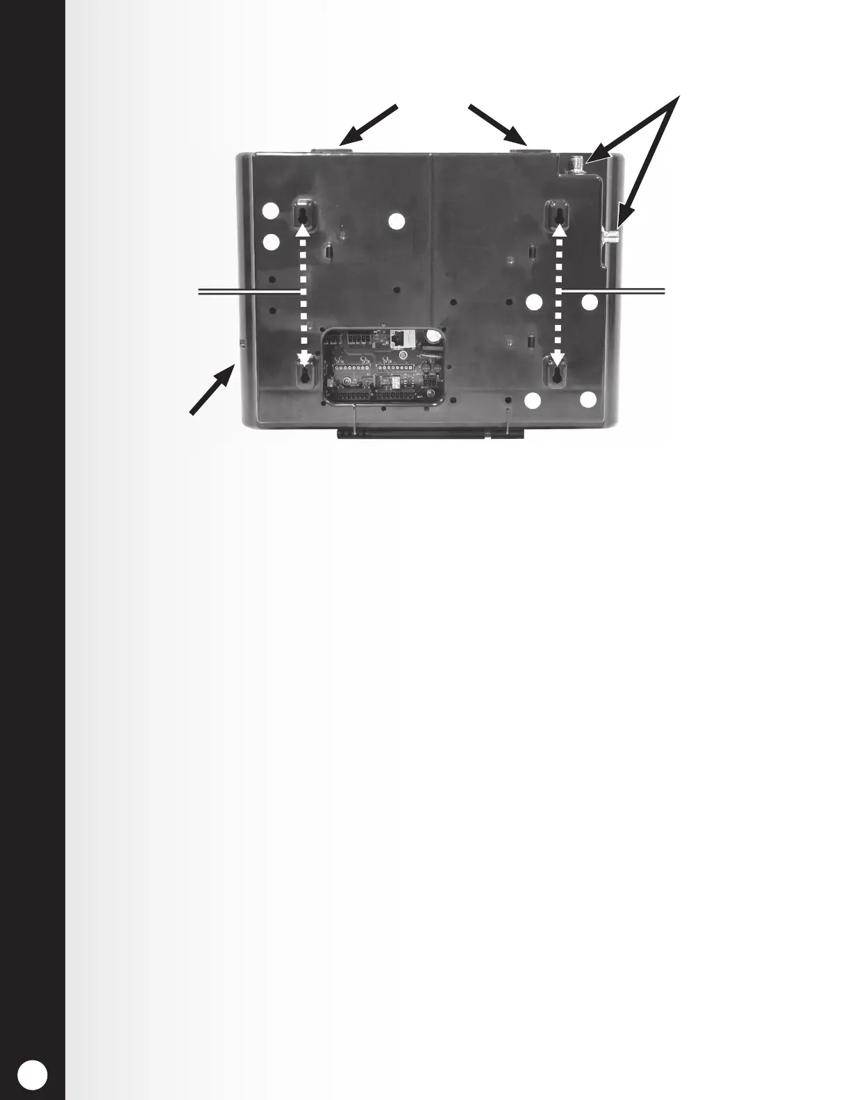
2.1.2 Rear and Side Panels
Antenna connectors
Reset switch
(recessed)
Screw holes for
mounting
Screw holes for
mounting
Cabinet latches
Figure 3. Base station rear panel features
h When the two cabinet latches located on top of the cabinet are pressed
simultaneously, the cabinet opens when pulling forward and down.
h The Antenna connectors are for screw-mounting the enclosed antennas.
h The four screw holes are used to mount the base station on the wall.
h The reset switch is used to perform a base station soft restart. It is located
in a small hole on the right side of the base station. To depress the reset
switch, push a small pointed object (such as paper clip) into the hole.
 Loading...