2222
Stripe Hog Systems
pressure is controlled by the RPM of the engine
and/or by adjusting the manual bypass valve on
the pump. Since engine RPM also controls the
level of vacuum, adjusting the pressure using the
manual bypass valve is benecial when maximum
engine RPM is required for vacuum and less than
maximum waterblasting pressure or gallons per
minute is desired for the material being removed
or the waterblasting tools being used.
The Ultra-high pressure pump produces up to
40,000 psi (2,758 BAR) with a ow rate of 12 gal-
lons (45 Liters) per minute at maximum engine
RPM. The gallons per minute (GPM) produced by
the Ultra-high pressure pump is controlled by
pump RPM, plunger diameter, length of stroke and
number of plungers. Once the Ultra-high pressure
pump is engaged it continually displaces water
provided by the charge water pump. The charge
water travels through the low pressure side of the
manifold of the Ultra-high pressure pump, then
through a set of 3 univalves into the 3 stung
boxes. The plungers then force the water back
through the high pressure side of the Univalves
and manifold. These Univalves are critical to the
operation of the ultra-high pressure pump as they
facilitate two functions at the same time. They al-
low the low pressure water from the charge water
pump to enter the stung box and the ultra-high
pressure water to ow into the ultra-high pressure
side of the manifold. Once the water is forced back
through the manifold it is directed out to the blast-
ing head or back to the clean water tank by the
diverter valve. Without these valves it would be
impossible to separate the high and low pressure
water from each other. Hog Technologies recom-
mends that you keep 3 fully serviced Univalves
in your spare parts system to prevent downtime.
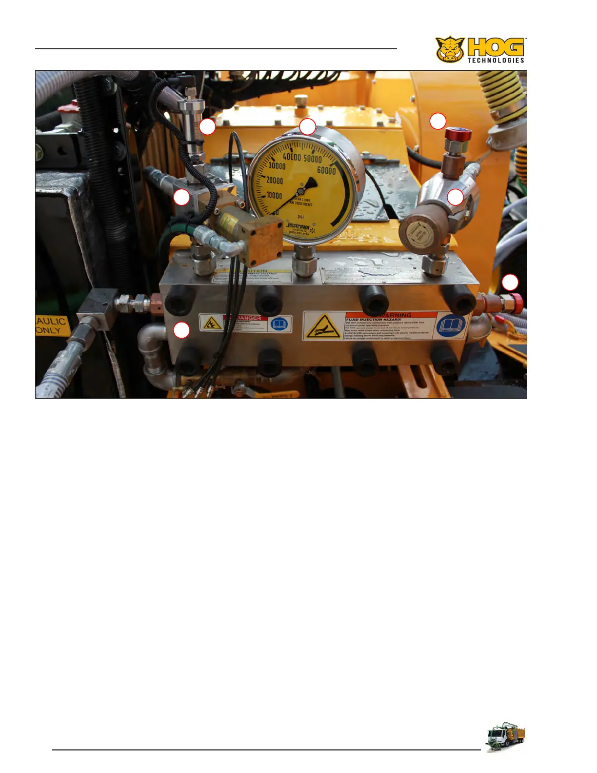
Ultra-High Pressure Pump Components
12
3
4
5
6
6
1. High Pressure Gauge 4. High Pressure Pump Manifold
2. High Pressure Sensor 5. Manual Bypass Valve
3. Diverter Valve 6. Rupture Discs
 Loading...