4545
Stripe Hog Systems
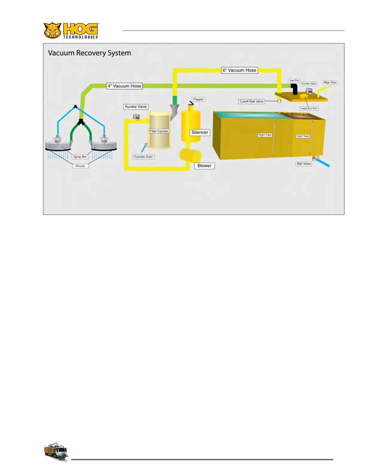
2.7 Vacuum Recovery System
Overview
The vacuum recovery system consists of a high
performance blower, vacuum hoses, lter canis-
ter, relief valves and a debris tank. The system is
powered by the main truck engine and activated
whenever the PTO and 40K Clutch is engaged.
The blower creates vacuum in the lter canister,
debris tank, vacuum hoses and blasting heads.
A lter located in the lter canister protects the
blower and exible hoses with quick disconnect
ttings provide vacuum to the truck mounted
blasting heads.
The vacuum recovery system is critical to pro-
ductivity on most waterblasting projects . Airport
specications require minimal FOD (foreign, ob-
jects, debris) after blasting as possible due to the
possibility of removal projects on active taxiways
and runways.
On road construction sites, vacuum recovery is
critical to productivity by removing excess water
and debris from the road surface. Paint crews are
generally on location to apply new line markings
immediately after existing markings have been
removed. The eciency of the vacuum system
in removing water and debris from the road sur-
face after blasting determines how quickly the
new markings can be applied. The waterblasting
vacuum recovery system only leaves a damp strip
of moisture on the road surface after removal al-
lowing painting shortly after blasting operations
are completed.
Proper Airow And Safety Valves
Maintaining maximum engine RPM and airow at
the blasting heads is essential for achieving opti-
mum vacuum performance. The vacuum blower
creates negative pressure in the blast head shroud
pulling air past the wear brush into the shroud,
then transporting air, water and debris from the
shroud through the 4” vacuum hose to the inlet
port on the debris tank. The water and debris is
separated from the airow and deposited into a
debris bag or directly into the tank, depending on
the truck options selected. The ow of air contin-
ues from the debris tank through the 6” vacuum
hose to the lter canister where the air is ltered
and residual water is separated and collected.
 Loading...