6969
Stripe Hog Systems
2.15 Waterblasting Hydraulic System
Overview
The hydraulic system is powered by the truck en-
gine and activated by the PTO switch in the console
switch panel. It is equipped with a pump, large
reservoir/cooling tank, a high pressure in-line lter
and a return lter near the reservoir ll tting.
An oil cooler with constant ON fans cools the
hydraulic uid during operation. Electric solenoid
valves activated by switches in the control switch
panel and joystick console direct hydraulic pres-
sure to the various components. Hydraulic oil level
and temperature are monitored by a site gauge
with an integrated thermometer on the side of
the reservoir. The hydraulic system provides the
hydraulic power for the Hog Arm, the thru-shaft
hydraulic motors that rotate the spray bars and
the charge water pump. It also provides hydrau-
lic power to the cylinders that unlock and lift the
debris tank door and to the cylinders that tilt the
debris tank to dump debris when the tank is full.
Hydraulic Circuit and Pump
The engine driven waterblasting accessory pump
is mounted to the OMSI gear case on the truck
chassis. It provides high pressure uid to the hydrau-
lic powered waterblasting accessory systems. Some
return uid is routed through the cooler mounted
on the forward side of the clean water tank that
removes excess heat from the uid whenever
any hydraulic system is in operation. The circuit
is equipped with two pressure relief valves, one
on the pump and one in the manifold that prevent
excessive pressure in the system. The maximum
operation pressure for the hydraulic system is
3000 psi (207 BAR).
Reservoir
A large reservoir tank mounted on the hydraulic
tree behind the cab provides the hydraulic uid for
the system. The pump circulates uid through the
manifold, motors, hydraulic cylinders and other
components, then back to the tank. A low pres-
sure lter near the reservoir ll tting cleans the
uid as it ows back into the reservoir.
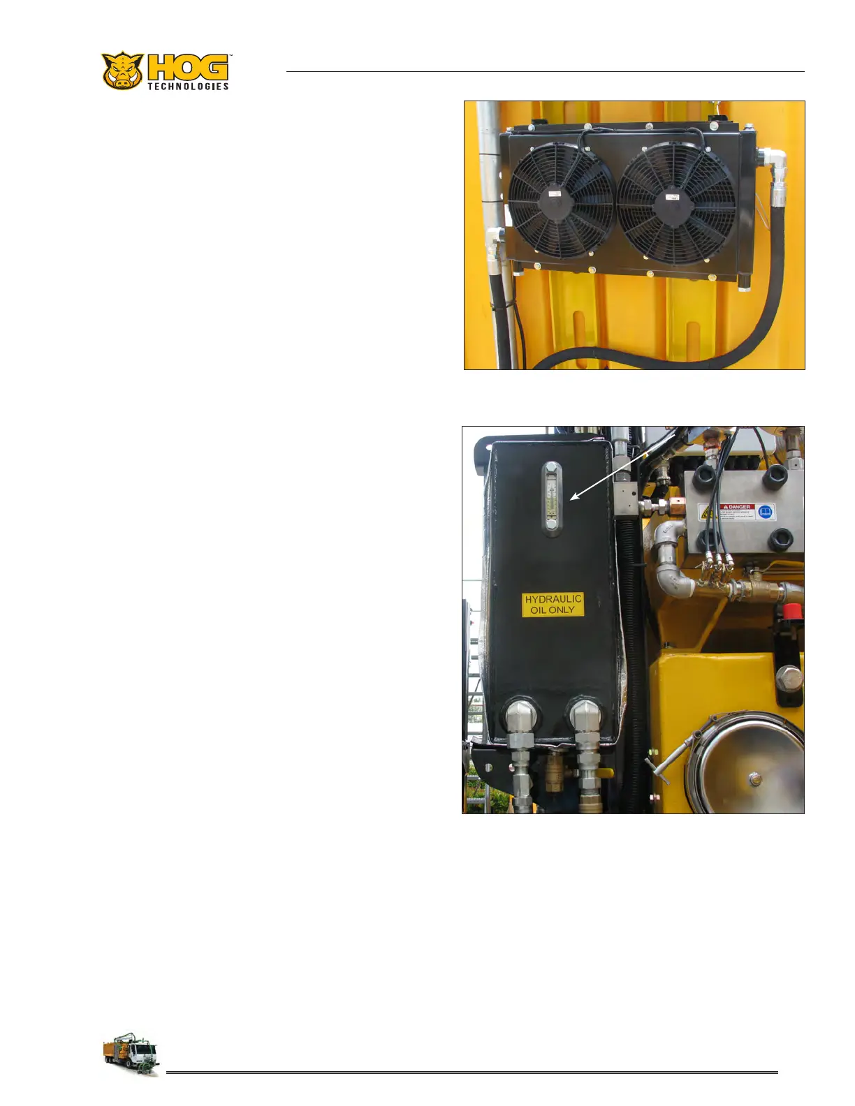
A sight glass and integrated thermometer is used
to monitor uid level and oil temperature. The
uid level should be maintained within the upper
level of the sight glass to ensure adequate uid
for operation.
Typical Hydraulic Reservoir & Sight Glass
Typical Hydraulic Fluid Cooler
Hydraulic uid should be changed and the tank
ushed on a regular schedule as stated in the
Waterblasting Maintenance Matrix located in the
Maintenance section of this manual.
 Loading...