2525
Stripe Hog Systems
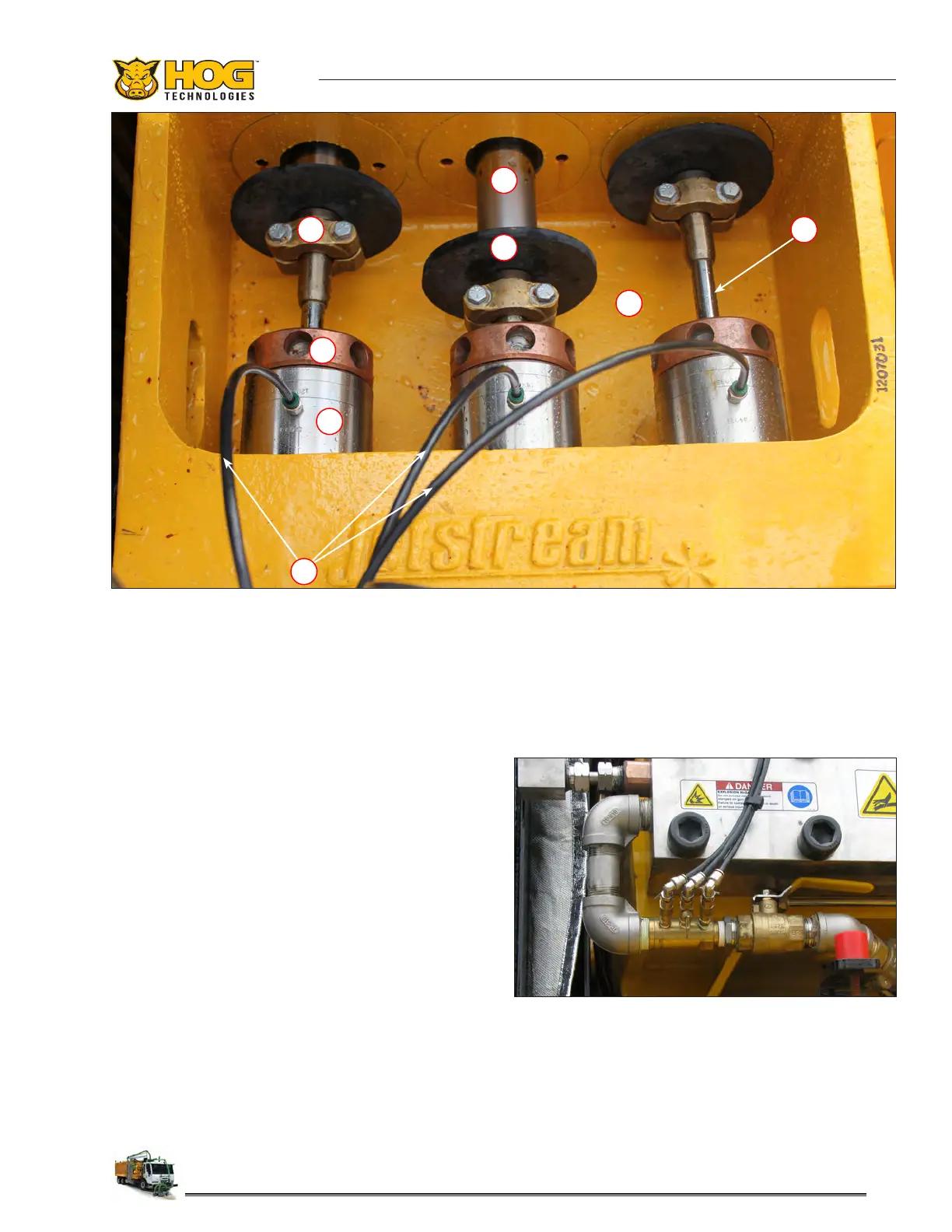
1. Coupling 5. Gland Nut
2. Pony Rod (Connecting Rod) 6. Stung Box
3. Deector 7. Lubrication Lines
4. Plunger 8. Bilge
UHP Pump Bilge & Bilge Compartment Components
1 4
3
2
6
7
5
8
Packing Lube Water And Bilge Pump
There are three (3) stung boxes, packing seals
and plungers in the Ultra-high pressure pump
that must be continuously lubricated and cooled
to achieve maximum life expectancy. Lubrication
and cooling water for the plungers and packing
seals is provided by lubrication lines connected to
the charge water supply line just below the ultra-
high pressure pump manifold.
A metering valve on each line controls the ow of
water to the stung box. The ow of water to the
stung box should be checked at the beginning of
each shift and periodically during operation. This
should be done with the PTO engaged, the charge
pump activated and the engine at idle. There
should be a steady ow of water from the back of
each gland nut. Insucient water ow to packing
glands could cause the stung box to overheat
and crack or damage to the packing seals or the
plunger. Packing seals can also be damaged if the
Charge Water Supply Line & Metering Valves
cooling and lubrication line metering valves are
open to wide, allowing excessive water ow to
packing glands. For more information on adjusting
the ow of the lubrication and cooling water refer
to Jetstream Operations manual.
 Loading...