Rev. 1.71 70 April 11, 2017 Rev. 1.71 71 April 11, 2017
HT66F002/HT66F0025/HT66F003/HT66F004
Cost-Effective A/D Flash MCU with EEPROM
HT66F002/HT66F0025/HT66F003/HT66F004
Cost-Effective A/D Flash MCU with EEPROM
bit2~0 ST0RP2~ ST0RP0:STMCCRP3-bitregister,comparedwiththeSTMCounterbit9~bit7
ComparatorPMatchPeriod
000:1024STM0clocks
001:128STM0clocks
010:256STM0clocks
011:384STM0clocks
100:512STM0clocks
101:640STM0clocks
110:768STM0clocks
111:896STM0clocks
ThesethreebitsareusedtosetupthevalueontheinternalCCRP3-bitregister,whicharethen
comparedwiththeinternalcounter’shighestthreebits.Theresultofthiscomparisoncanbe
selectedtocleartheinternalcounteriftheST0CCLRbitissettozero.SettingtheST0CCLRbit
tozeroensuresthatacomparematchwiththeCCRPvalueswillresettheinternalcounter.Asthe
CCRPbitsareonlycomparedwiththehighestthreecounterbits,thecomparevaluesexistin128
clockcyclemultiples.Clearingallthreebitstozeroisineffectallowingthecountertooverow
atitsmaximumvalue.
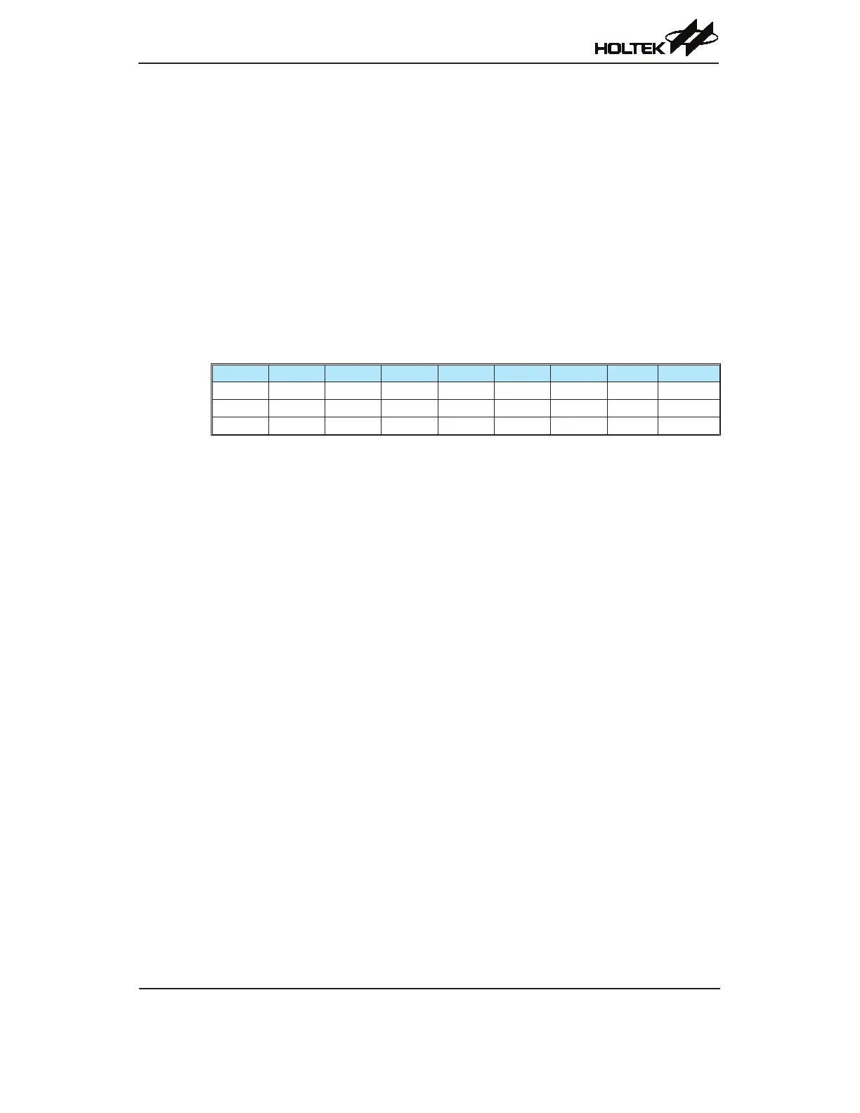
STM0C1 Register
Bit 7 6 5 4 3 2 1 0
Name ST0M1 ST0M0 ST0IO1 ST0IO0 ST0OC ST0POL ST0DPX ST0CCLR
R/W R/W R/W R/W R/W R/W R/W R/W R/W
POR 0 0 0 0 0 0 0 0
bit7~6 ST0M1~ ST0M0:SelectSTM0OperatingMode
00:CompareMatchOutputMode
01:CaptureInputMode
10:PWMoutputModeorSinglePulseOutputMode
11:Timer/CounterMode
ThesebitssetuptherequiredoperatingmodefortheSTM.ToensurereliableoperationtheSTM
shouldbeswitchedoffbeforeanychangesaremadetotheST0M1andST0M0bits.IntheTimer/
CounterMode,theSTMoutputpinstateisundened.
bit5~4 ST0IO1~ ST0IO0:SelectSTM0function
CompareMatchOutputMode
00:Nochange
01:Outputlow
10:Outputhigh
11:Toggleoutput
PWMoutputMode/SinglePulseOutputMode
00:PWMOutputinactivestate
01:PWMOutputactivestate
10:PWMoutput
11:Singlepulseoutput
CaptureInputMode
00:InputcaptureatrisingedgeofSTP0I
01:InputcaptureatfallingedgeofSTP0I
10:Inputcaptureatfalling/risingedgeofSTP0I
11:Inputcapturedisabled
Timer/counterMode:
Unused
ThesetwobitsareusedtodeterminehowtheTMoutputpinchangesstatewhenacertain
conditionisreached.ThefunctionthatthesebitsselectdependsuponinwhichmodetheTMis
running.