Rev. 1.50 156 August 28, 2017 Rev. 1.50 157 August 28, 2017
HT66F0175/HT66F0185
A/D Flash MCU with EEPROM
HT66F0175/HT66F0185
A/D Flash MCU with EEPROM
UART External Pin
Tocommunicatewithanexternalserialinterface,theinternalUARThastwoexternalpinsknown
asTXandRX.TheTXandRXpinsarerespectivelytheUARTtransmitterandreceiverpinswhich
arepin-sharedwithI/Oorotherpin-sharedfunctions.AlongwiththeUARTENbit,theTXENand
RXENbits,ifset,willautomaticallysetuptheseI/OpinstotheirrespectiveTXoutputandRXinput
conditionsanddisableanypull-highresistoroptionwhichmayexistontheTXandRXpins.When
theTXorRXpinfunctionisdisabledbyclearingtheUARTEN,TXENorRXENbit,theTXorRX
pinwillbeusedasI/Oorotherpin-sharedfunctionalpindependinguponthepin-sharedfunction
priority.
UART Data Transfer Scheme
TheabovediagramshowstheoveralldatatransferstructurearrangementfortheUARTinterface.
TheactualdatatobetransmittedfromtheMCUisfirsttransferredtotheTXRregisterbythe
applicationprogram.ThedatawillthenbetransferredtotheTransmitShiftRegisterfromwhereit
willbeshiftedout,LSBrst,ontotheTXpinataratecontrolledbytheBaudRateGenerator.Only
theTXRregisterismappedontotheMCUDataMemory,theTransmitShiftRegisterisnotmapped
andisthereforeinaccessibletotheapplicationprogram.
DatatobereceivedbytheUARTisacceptedontheexternalRXpin,fromwhereitisshiftedin,
LSBfirst,totheReceiverShiftRegisterataratecontrolledbytheBaudRateGenerator.When
theshiftregisterisfull,thedatawillthenbetransferredfromtheshiftregistertotheinternalRXR
register,whereitisbufferedandcanbemanipulatedbytheapplicationprogram.OnlytheTXR
registerismappedontotheMCUDataMemory,theReceiverShiftRegisterisnotmappedandis
thereforeinaccessibletotheapplicationprogram.
Itshouldbenotedthattheactualregisterfordatatransmissionandreception,althoughreferredto
inthetext,andinapplicationprograms,asseparateTXRandRXRregisters,onlyexistsasasingle
sharedregisterintheDataMemory.ThissharedregisterknownastheTXR_RXRregisterisused
forbothdatatransmissionanddatareception.
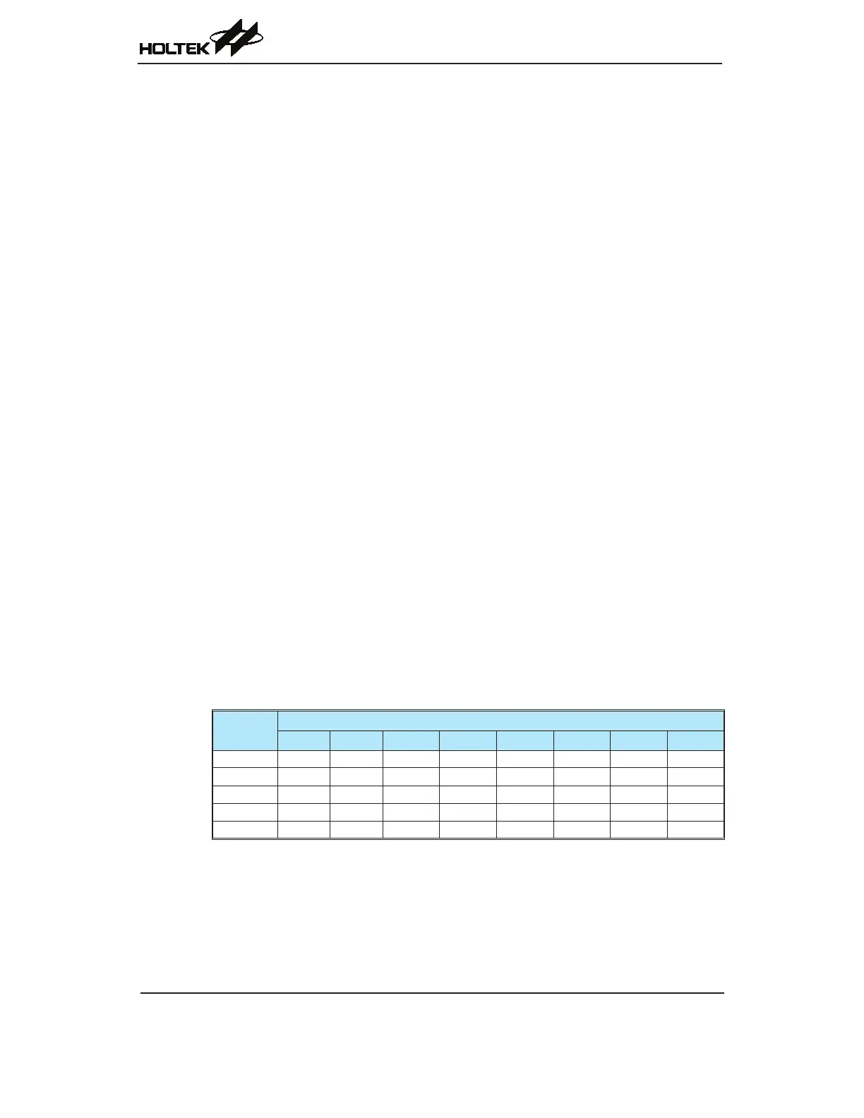
UART Status and Control Registers
TherearevecontrolregistersassociatedwiththeUARTfunction.TheUSR,UCR1andUCR2
registerscontroltheoverallfunctionoftheUART,whiletheBRGregistercontrolstheBaudrate.
TheactualdatatobetransmittedandreceivedontheserialinterfaceismanagedthroughtheTXR_
RXRdataregisters.
Register
Name
Bit
7 6 5 4 3 2 1 0
USR PERR NF FERR OERR RIDLE RXIF TIDLE TXIF
UCR1 UARTEN BNO PREN PRT STOPS TXBRK RX8 TX8
UCR2 TXEN RXEN BRGH ADDEN WAKE RIE TIIE TEIE
BRG BRG7 BRG6 BRG5 BRG4 BRG3 BRG2 BRG1 BRG0
TXR_RXR TXRX7 TXRX6 TXRX5 TXRX4 TXRX3 TXRX2 TXRX1 TXRX0
UART Status and Control Registers List – HT66F0185 only