Rev. 1.50 162 August 28, 2017 Rev. 1.50 163 August 28, 2017
HT66F0175/HT66F0185
A/D Flash MCU with EEPROM
HT66F0175/HT66F0185
A/D Flash MCU with EEPROM
UART Setup and Control
Fordatatransfer,theUARTfunctionutilizesanon-return-to-zero,morecommonlyknownasNRZ,
format.Thisiscomposedofonestartbit,eightorninedatabitsandoneortwostopbits.Parity
issupportedbytheUARThardwareandcanbesetuptobeeven,oddornoparity.Forthemost
commondataformat,8databitsalongwithnoparityandonestopbit,denotedas8,N,1,isused
asthedefaultsetting,whichisthesettingatpower-on.Thenumberofdatabitsandstopbits,along
withtheparity,aresetupbyprogrammingthecorrespondingBNO,PRT,PRENandSTOPSbitsin
theUCR1register.Thebaudrateusedtotransmitandreceivedataissetupusingtheinternal8-bit
baudrategenerator,whilethedataistransmittedandreceivedLSBrst.Althoughthetransmitter
andreceiveroftheUARTarefunctionallyindependent,theybothusethesamedataformatandbaud
rate.Inallcasesstopbitswillbeusedfordatatransmission.
Enabling/Disabling the UART Interface
Thebasicon/offfunctionoftheinternalUARTfunctioniscontrolledusingtheUARTENbitinthe
UCR1register.IftheUARTEN,TXENandRXENbitsareset,thenthesetwoUARTpinswillact
asnormalTXoutputpinandRXinputpinrespectively.IfnodataisbeingtransmittedontheTX
pin,thenitwilldefaulttoalogichighvalue.
ClearingtheUARTENbitwilldisabletheTXandRXpinsandthesetwopinswillbeusedasI/
Oorotherpin-sharedfunctionalpins.WhentheUARTfunctionisdisabled,thebufferwillbe
resettoanemptycondition,atthesametimediscardinganyremainingresidualdata.Disablingthe
UARTwillalsoresettheenablecontrol,theerrorandstatusagswithbitsTXEN,RXEN,TXBRK,
RXIF,OERR,FERR,PERRandNFbeingclearedwhilebitsTIDLE,TXIFandRIDLEwillbe
set.TheremainingcontrolbitsintheUCR1,UCR2andBRGregisterswillremainunaffected.
IftheUARTENbitintheUCR1registerisclearedwhiletheUARTisactive,thenallpending
transmissionsandreceptionswillbeimmediatelysuspendedandtheUARTwillberesettoa
conditionasdenedabove.IftheUARTisthensubsequentlyre-enabled,itwillrestartagaininthe
sameconguration.
Data, Parity and Stop Bit Selection
Theformatofthedatatobetransferrediscomposedofvariousfactorssuchasdatabitlength,
parityon/off,paritytype,addressbitsandthenumberofstopbits.Thesefactorsaredeterminedby
thesetupofvariousbitswithintheUCR1register.TheBNObitcontrolsthenumberofdatabits
whichcanbesettoeither8or9.ThePRTbitcontrolsthechoiceifoddorevenparity.ThePREN
bitcontrolstheparityon/offfunction.TheSTOPSbitdecideswhetheroneortwostopbitsareto
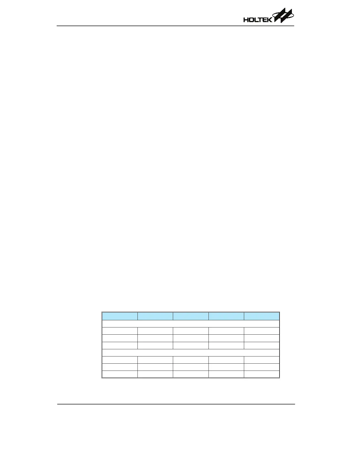
beused.Thefollowingtableshowsvariousformatsfordatatransmission.Theaddressdetectmode
controlbitidentiestheframeasanaddresscharacter.Thenumberofstopbits,whichcanbeeither
oneortwo,isindependentofthedatalength.
Start Bit Data Bits Address Bits Parity Bit Stop Bit
Example of 8-bit Data Formats
1 8 0 0 1
1 7 0 1 1
1 7 1 0 1
Example of 9-bit Data Formats
1 9 0 0 1
1 8 0 1 1
1 8 1 0 1
Transmitter Receiver Data Format