Rev. 1.50 140 August 28, 2017 Rev. 1.50 141 August 28, 2017
HT66F0175/HT66F0185
A/D Flash MCU with EEPROM
HT66F0175/HT66F0185
A/D Flash MCU with EEPROM
Bit0 RXAK:I
2
Cbusreceiveacknowledgeag
0:Slavereceivesacknowledgeag
1:Slavedoesnotreceiveacknowledgeag
TheRXAKflagisthereceiveracknowledgeflag.WhentheRXAKflagis“0”,it
meansthataacknowledgesignalhasbeenreceivedatthe9thclock,after8bitsofdata
havebeentransmitted.Whentheslavedeviceinthetransmitmode,theslavedevice
checkstheRXAKagtodetermineifthemasterreceiverwishestoreceivethenext
byte.TheslavetransmitterwillthereforecontinuesendingoutdatauntiltheRXAK
agis“1”.Whenthisoccurs,theslavetransmitterwillreleasetheSDAlinetoallow
themastertosendaSTOPsignaltoreleasetheI
2
CBus.
I
2
C Bus Communication
CommunicationontheI
2
Cbusrequiresfourseparatesteps,aSTARTsignal,aslavedeviceaddress
transmission,adatatransmissionandfinallyaSTOPsignal.WhenaSTARTsignalisplacedon
theI
2
Cbus,alldevicesonthebuswillreceivethissignalandbenotiedoftheimminentarrivalof
dataonthebus.Therstsevenbitsofthedatawillbetheslaveaddresswiththerstbitbeingthe
MSB.Iftheaddressoftheslavedevicematchesthatofthetransmittedaddress,theHAASbitinthe
SIMC1registerwillbesetandanI
2
Cinterruptwillbegenerated.Afterenteringtheinterruptservice
routine,theslavedevicemustrstchecktheconditionoftheHAASandSIMTOFbitstodetermine
whethertheinterruptsourceoriginatesfromanaddressmatch,8-bitdatatransfercompletionor
I
2
Cbustime-outoccurrence.Duringadatatransfer,notethatafterthe7-bitslaveaddresshasbeen
transmitted,thefollowingbit,whichisthe8thbit,istheread/writebitwhosevaluewillbeplacedin
theSRWbit.Thisbitwillbecheckedbytheslavedevicetodeterminewhethertogointotransmitor
receivemode.BeforeanytransferofdatatoorfromtheI
2
Cbus,themicrocontrollermustinitialise
thebus,thefollowingarestepstoachievethis:
• Step1
SettheSIM2~SIM0bitsto“110”andSIMENbitto“1”intheSIMC0registertoenabletheI
2
C
bus.
• Step2
WritetheslaveaddressofthedevicetotheI
2
CbusaddressregisterSIMA.
• Step3
SettheSIMEinterruptenablebitoftheinterruptcontrolregistertoenabletheSIMinterrupt.
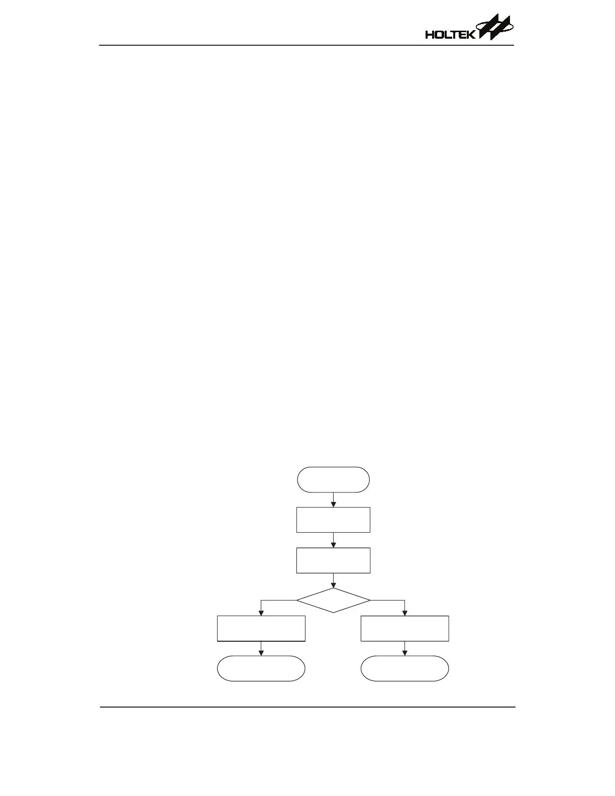
I
2
C Bus Initialisation Flow Chart