Rev. 1.50 168 August 28, 2017 Rev. 1.50 169 August 28, 2017
HT66F0175/HT66F0185
A/D Flash MCU with EEPROM
HT66F0175/HT66F0185
A/D Flash MCU with EEPROM
Address Detect Mode
SettingtheAddressDetectfunctionenablecontrolbit,ADDEN,intheUCR2register,enablesthis
specialfunction.Ifthisbitissetto1,thenanadditionalqualierwillbeplacedonthegeneration
ofaReceiverDataAvailableinterrupt,whichisrequestedbytheRXIFflag.IftheADDENbit
isequalto1,thenwhenthedataisavailable,aninterruptwillonlybegenerated,ifthehighest
receivedbithasahighvalue.NotethattherelatedinterruptenablecontrolbitandtheEMIbitofthe
microcontrollermustalsobeenabledforcorrectinterruptgeneration.Thehighestaddressbitisthe
9
th
bitifthebitBNO=1orthe8
th
bitifthebitBNO=0.Ifthehighestbitishigh,thenthereceived
wordwillbedenedasanaddressratherthandata.ADataAvailableinterruptwillbegenerated
everytimethelastbitofthereceivedwordisset.IftheADDENbitisequalto0,thenaReceive
DataAvailableinterruptwillbegeneratedeachtimetheRXIFagisset,irrespectiveofthedatalast
butstatus.Theaddressdetectionandparityfunctionsaremutuallyexclusivefunctions.Therefore,if
theaddressdetectfunctionisenabled,thentoensurecorrectoperation,theparityfunctionshouldbe
disabledbyresettingtheparityfunctionenablebitPRENtozero.
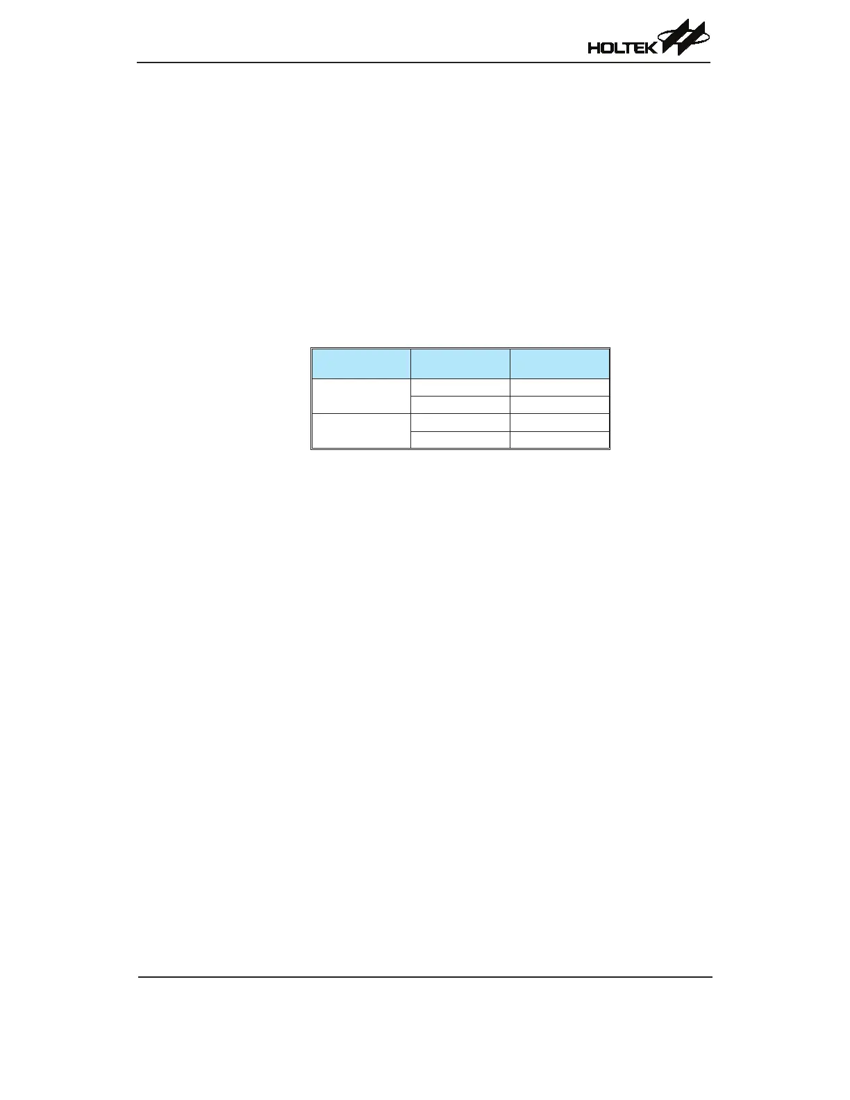
ADDEN
Bit 9 if BNO=1
Bit 8 if BNO=0
UART Interrupt
Generated
0
0 √
1 √
1
0 X
1 √
ADDEN Bit Function
UART Power Down and Wake-up
WhentheMCUsystemclockisswitchedoff,theUARTwillceasetofunction.IftheMCUexecutes
the“HALT”instructionandswitchesoffthesystemclockwhileatransmissionisstillinprogress,
thenthetransmissionwillbepauseduntiltheUARTclocksourcederivedfromthemicrocontroller
isactivated.Inasimilarway,iftheMCUexecutesthe“HALT”instructionandswitchesoffthe
systemclockwhilereceivingdata,thenthereceptionofdatawilllikewisebepaused.Whenthe
MCUenterstheIDLEorSLEEPMode,notethattheUSR,UCR1,UCR2,transmitandreceive
registers,aswellastheBRGregisterwillnotbeaffected.Itisrecommendedtomakesurerstthat
theUARTdatatransmissionorreceptionhasbeenfinishedbeforethemicrocontrollerentersthe
powerdownmode.
TheUARTfunctioncontainsareceiverRXpinwake-upfunction,whichisenabledordisabled
bytheWAKEbitintheUCR2register.Ifthisbit,alongwiththeUARTenablebit,UARTEN,the
receiverenablebit,RXENandthereceiverinterruptbit,RIE,areallsetbeforetheMCUentersthe
IDLE0orSLEEPMode,thenafallingedgeontheRXpinwillwakeuptheMCUfromtheIDLE0
orSLEEPMode.Notethatasittakescertainsystemclockcyclesafterawake-up,beforenormal
microcontrolleroperationresumes,anydatareceivedduringthistimeontheRXpinwillbeignored.
ForaUARTwake-upinterrupttooccur,inadditiontothebitsforthewake-upbeingset,theglobal
interruptenablebit,EMI,andtheUARTinterruptenablebit,URE,mustbeset.IftheEMIandURE
bitsarenotsetthenonlyawakeupeventwilloccurandnointerruptwillbegenerated.Notealso
thatasittakescertainsystemclockcyclesafterawake-upbeforenormalmicrocontrollerresumes,
theUARTinterruptwillnotbegenerateduntilafterthistimehaselapsed.