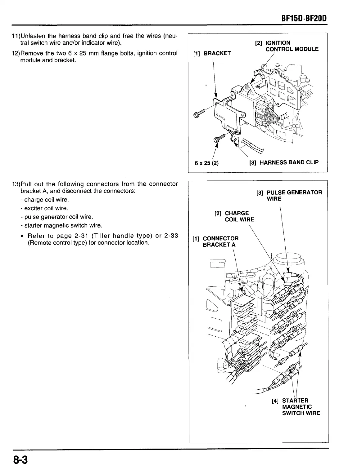
11)Unfasten the harness band clip and free the wires (neu-
tral switch wire and/or indicator wire).
12)Remove the two
6
x
25
mm flange bolts, ignition control
13)Pull out the following connectors
,;om
the connector
bracket
A,
and disconnect the connectors:
-
charge coil wire.
-
exciter coil wire.
-
pulse generator coil wire.
-
starter magnetic switch wire.
Refer to page 2-31 (Tiller handle type) or 2-33
(Remote control type) for connector location.
[2] IGNITION
CONTROL MODULE
[l] BRACKET
/
I
6x25(2)
[3] HARNESS BAND CLIP
[a]
PULSE GENERATOR
WIRE
[l]
CONNECTOR
BRACKET A
[4]
STARTER
MAGNETIC
SWITCH WIRE
 Loading...