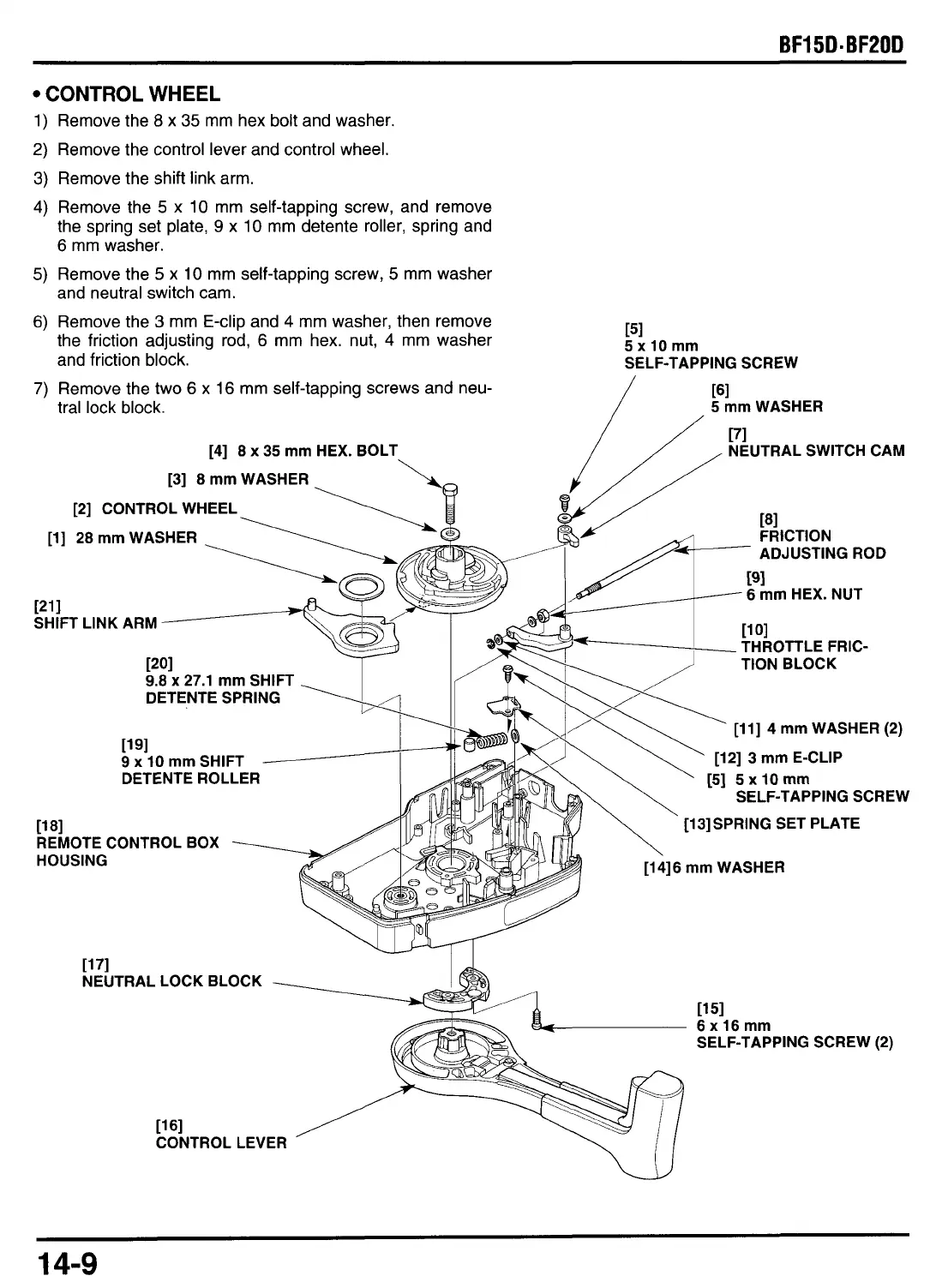
CONTROL WHEEL
Remove the
8
x
35
mm hex bolt and washer.
Remove the control lever and control wheel.
Remove the shift link arm.
Remove the
5
x 10 mm self-tapping screw, and remove
the spring set plate,
9
x
10 mm detente roller, spring and
6
mm washer.
Remove the
5
x
10
mm self-tapping screw,
5
mm washer
and neutral switch cam.
Remove the
3
mm E-clip and
4
mm washer, then remove
the friction adjusting rod, 6 mm hex. nut,
4
mm washer
Remove the two 6
x
16 mm self-tapping screws and neu-
tral lock block.
151
5xlOmm
and friction block.
SELF-TAPPING SCREW
5
mm
WASHER
[71
NEUTRAL SWITCH CAM
[4]
8
x 35 mm
HEX. BOLT
.
[3]
8
mm
WASHER
[2]
CONTROL WHEEL
[l] 28 mm
WASHER
ADJUSTING ROD
6 mm
HEX. NUT
1211
SHIFT LINK ARM
THROTTLE FRIC-
9.8
x
27.1 mm
SHIFT
DETENTE SPRING
[ll] 4 mm
WASHER
(2)
[12] 3 mm
E-CLIP
9 x 10 mm
SHIFT
DETENTE ROLLER
SELF-TAPPING SCREW
[13]SPRING
SET PLATE
11 81
REMOTE CONTROL BOX
HOUSING
11 71
NEUTRAL LOCK BLOCK
--
[161
CONTROL LEVER
[i 51
k-
6xl6mm
SELF-TAPPING SCREW
(2)
14-9


 To Next Page