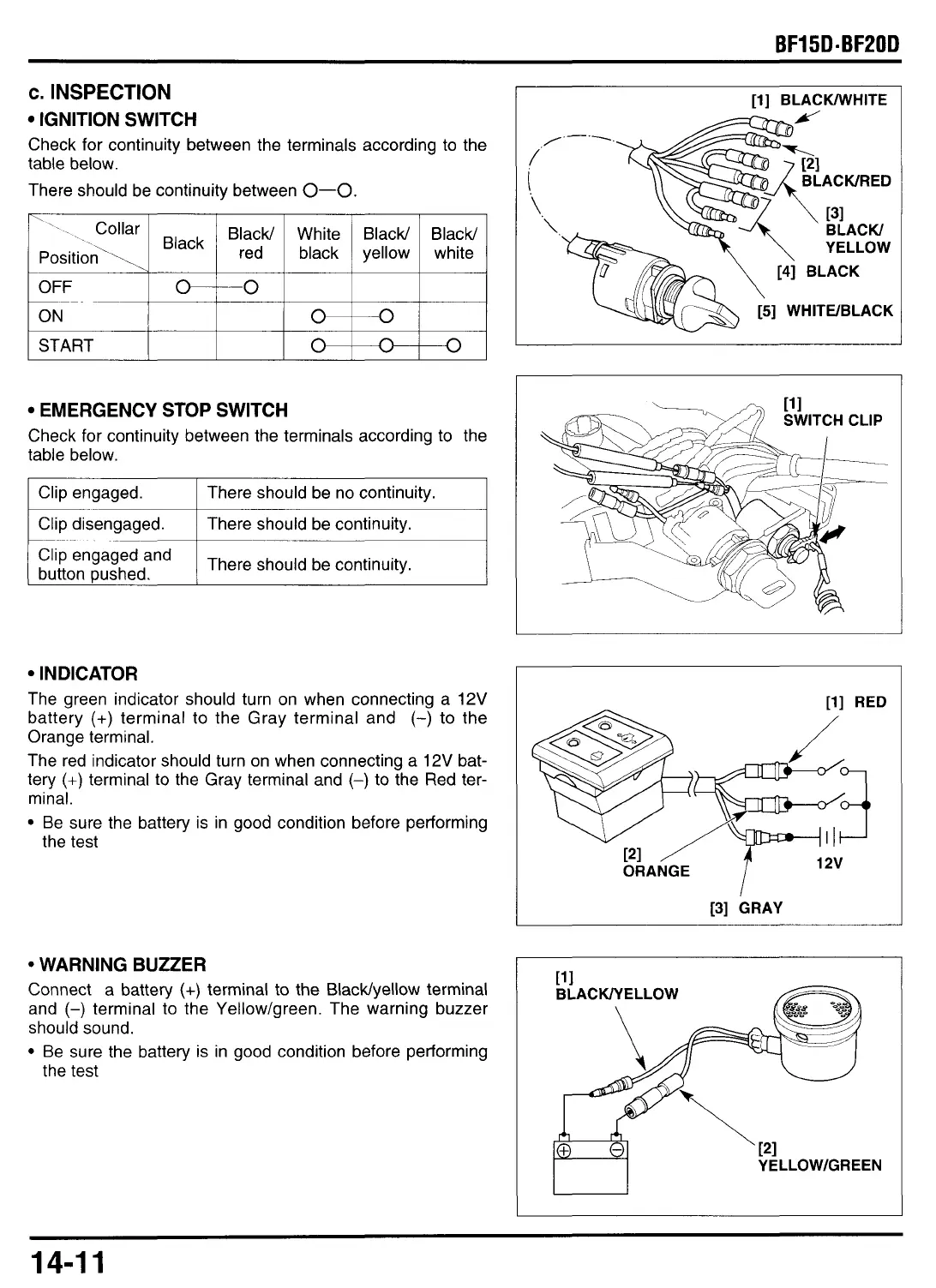
c.
INSPECTION
IGNITION SWITCH
Check for continuity between the terminals according
to
the
table below.
\
OFF
ON
START
~~
rhere should be continuity between
0-0.
*--0
~ ~~~
0 0
0
n
0
Collar Black/ White Black/ Black/
1
red
~
black
~
yellow
,
white
‘,
Black
Position\
~
EMERGENCY STOP SWITCH
Check for continuity between the terminals according to the
table below.
I
Clip engaged.
I
There should be no continuity.
I
‘lip
engaged
and
I
There should be continuity.
button pushed.
IN DIC AT0
R
The green indicator should turn on when connecting a
12V
battery
(+)
terminal to the Gray terminal and
(-)
to
the
Orange terminal.
The red indicator should turn on when connecting a
12V
bat-
tery
(+)
terminal to the Gray terminal and
(-)
to the Red ter-
minal.
Be sure the battery is in good condition before performing
the test
WARNING BUZZER
Connect a battery
(+)
terminal to the BlacWyellow terminal
and
(-)
terminal
to
the Yellow/green. The warning buzzer
should sound.
Be sure the battery is in good condition before performing
the test
I
[l]
BLACWHITE
[5]
WHITWBLACK
SWITCH CLIP
[l] RED
/
[3]
GRAY
YE
LLOWIGREEN
14-1
1