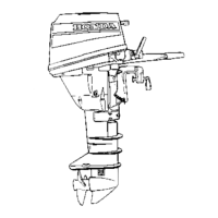
7.
RECOIL
STARTER
BF15DoBFZOD
I
1.
STARTER CASE
B
I
11
1
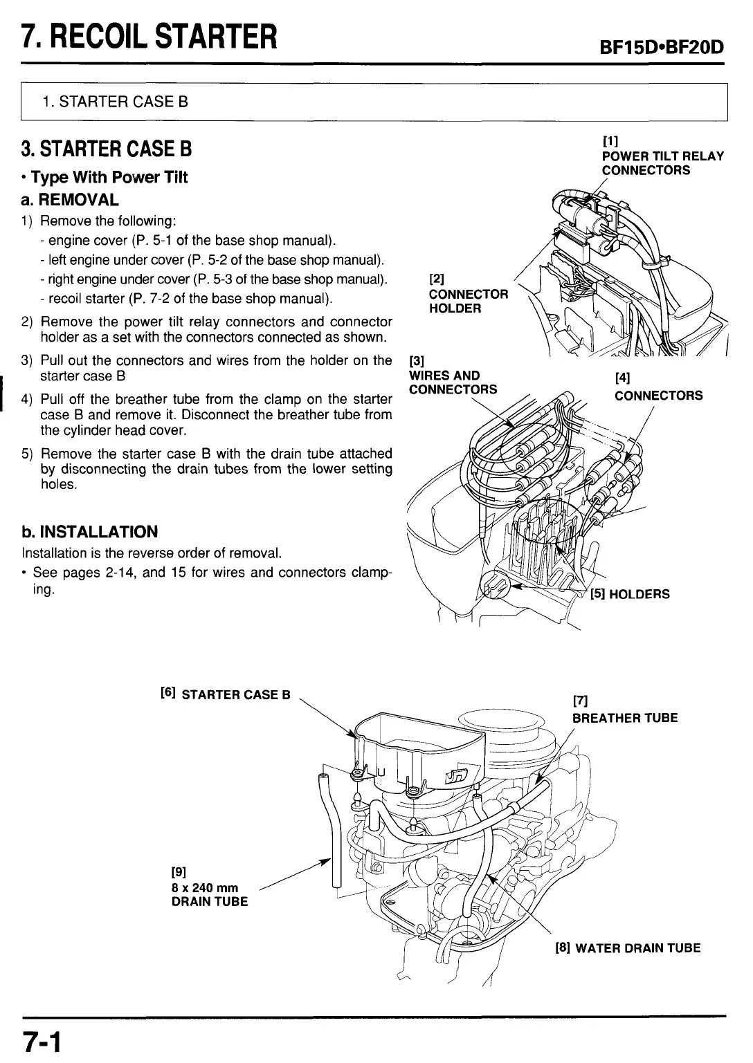
3.
STARTER
CASE
B
POWER TILT RELAY
CONNECTORS
Type
With
Power
Tilt
a. REMOVAL
1)
Remove the following:
-
engine cover (P. 5-1 of the base shop manual).
-
left engine under cover (P. 5-2 of the base shop manual).
-
recoil starter (P. 7-2 of the base shop manual).
2) Remove the power tilt relay connectors and connector
holder as a set with the connectors connected as shown.
3) Pull out the connectors and wires from the holder on the
-
right engine under cover (P. 5-3 of the base shop manual).
121
CONNECTOR
HOLDER
[3]
starter case
B
4) Pull off the breather tube from the clamp on the starter
case
B
and remove it. Disconnect the breather tube from
the cylinder head cover.
5)
Remove the starter case
B
with the drain tube attached
by disconnecting the drain tubes from the lower setting
holes.
b.
INSTALLATION
Installation is the reverse order
of
removal.
See pages 2-14, and 15 for wires and connectors clamp-
ing.
WIRES AND
141
161
STARTER CASE B
EATHER TUBE
191
8
x
240
mm
DRAIN TUBE
181
WATER DRAIN TUBE
7-
1
 Loading...