33-00462—05 8
Fig. 11.
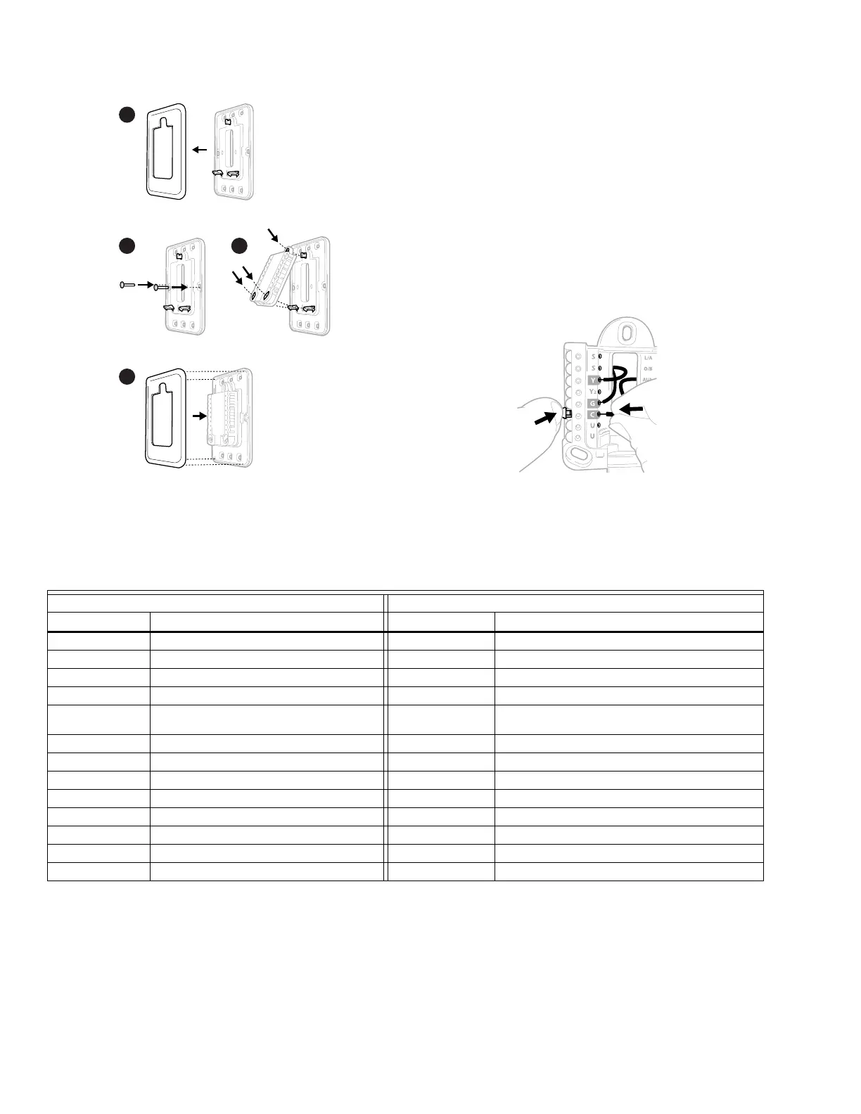
Wiring UWP
NOTE: If T10+ & EIM are used, UWP only wires to R and C
of a 24 VAC power supply. Usually R and C from
UWP goes to R & C at upper right of EIM.
Push down on the tabs to put the wires into the inner holes of
their corresponding terminals on the UWP (one wire per
terminal) until they are firmly in place.
Gently tug on the wires to verify they are secure.
If you need to release the wires again, push down the terminal
tabs on the sides of the UWP. This wiring is just an example,
yours may vary.
Fig. 12.
Terminal Designations
Table 7. Terminals on T10 or T10+ Without EIM
* The THP9045A C-wire adapter is used on heat/cool systems when you only have four wires at the thermostat and you need an
extra wire for a common wire. Use the K terminal in place of the Y and G terminals on conventional or heat pump systems to
provide control of the fan and the compressor through a single wire the unused wire then becomes your common wire. See
THP9045 instructions for more information.
** See note on Wiring U terminals on the following page.
Use 2x
supplied
screws
#6 5/8”
8
7
6
5
M37787
M37788
Conventional Systems Heat Pump Systems
Terminal Description Terminal Description
S/S Input for a wired sensor S/S Sensor options in charts on page 4
Y Compressor Stage 1 Y Compressor Stage 1
Y2 Compressor Stage 2 Y2 Compressor Stage 2
G Fan Relay G Fan Relay
C 24VAC Common wire from secondary side of
cooling transformer (if 2 transformers)
C 24VAC Common wire from secondary side of cooling
transformer
K* Connect to K on C-wire adapter K* Connect to K on C-wire adapter
U/U** Relay for humidifier, dehumidifier, or ventilator U/U** Relay for humidifier, dehumidifier, or ventilator
A L/A Connect to compressor monitor
W Heat Stage 1 O/B Changeover valve for heat pumps
W2 Heat Stage 2 AUX Backup Heat
E Emergency Heat
R 24 VAC Heating transformer R 24 VAC Heating transformer
Rc 24 VAC Cooling transformer Rc 24 VAC Cooling transformer
 Loading...