33-00462—05 16
INSTALLING EQUIPMENT
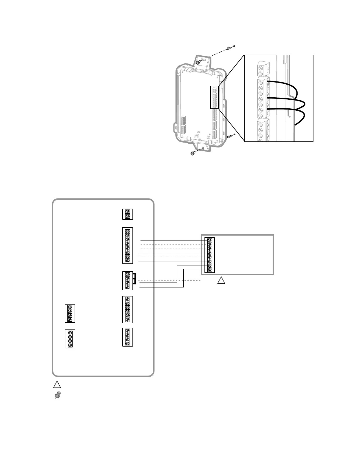
INTERFACE MODULE (IF USED)
1. Mount the EIM near the HVAC equipment or on the
equipment itself. Use screws and anchors as
appropriate for the mounting surface.
2. To wire the EIM, strip 1/4” insulation, then insert wires
(see Fig. 34. For wiring diagrams, see “EIM Wiring” on
following pages.)
Fig. 34.
EIM Wiring Diagrams
Fig. 35. Typical wiring of a conventional system with up to 3 stage heat and 2 stage cool with one transformer
M34247A
CONNECT
CONNECTED
M38709
Strip 1/4" insulation, then
insert wires as shown.
R
C
U3
U3
U2
U2
U1
S2
S2
S1
S1
S4
S4
S3
S3
THM04R3000
U1
Y2
G
L
W1
W2
AUX1
W3
AUX2
Y1
RH
RC
R
C
SENSORS
SENSORS DRY CONTACT OUTPUTS
24 V A C TO
THERMOSTAT
O/B
FURNACE
G (FAN)
R (24 VAC HOT)
W1 (HE AT STAG E 1 )
W2 (HE AT STAG E 2 )
Y1 (COMPRESSOR STAG E 1 )
Y2 (COMPRESS OR STAGE 2 )
C (24 VAC COMMON)
JUMPERS
W3 (HE AT STAG E 3 )
11
1
24 V A C
POWER
REMOVE JUMPER(S) IF USING SEPARATE TRANSFORMERS.
NOTE: SEE FOLLOWING PAGES FOR ADDITIONAL THERMOSTAT WIRING GUIDELINES FOR OTHER SYSTEM TYPES, SENSOR WIRING,
IAQ CONTROL, AND OTHER DRY CONTACT WIRING OPTIONS.
M38714
1

 Loading...