7 33-00462—05
SYSTEM INSTALLATION
When Installing This Product...
1. Read these instructions carefully. Failure to follow the
instructions can damage the product or cause a
hazardous condition.
2. Check the ratings given in the instructions to make sure
the product is suitable for your application.
3. Installer must be a trained, experienced service
technician.
4. After completing installation, use these instructions to
verify the product operation.
Finding Your Password (Date Code)
You will need the thermostat password to:
• Add or remove RedLINK 3.0 accessories
• Make changes to Installer Setup
• Perform an Installer Test
• Reset Thermostat to Factory Default Settings
To find the password (date code) Press the menu (three
horizontal lines) Scroll down and select “Dealer Information”.
CAUTION
Electrical Hazard.
Can cause electrical shock or equipment
damage.
Disconnect power before wiring.
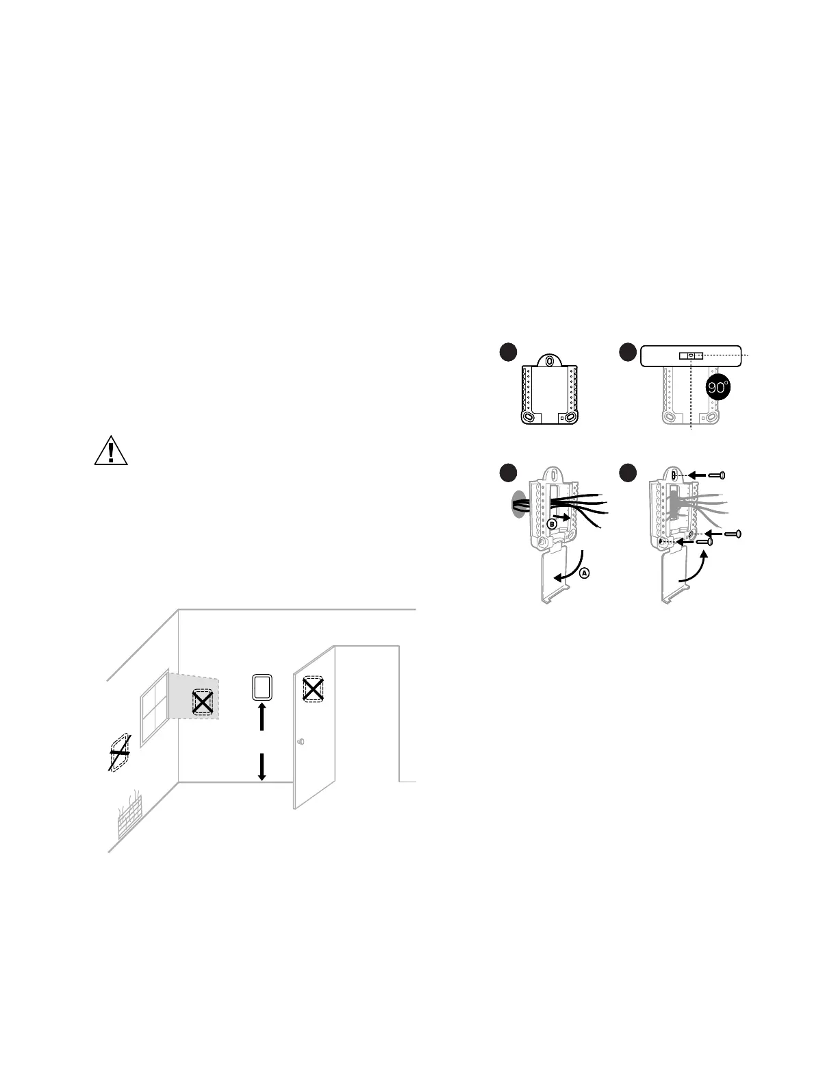
Selecting Thermostat Location
Install the thermostat about 5 ft. (1.5m) above the floor in an
area with good air circulation at average temperature. See
Fig. 9.
Fig. 9. Selecting thermostat location
Do not install the thermostat where it can be affected by:
— Drafts or dead spots behind doors and in corners
— Hot or cold air from ducts
— Radiant heat from sun or appliances
— Concealed pipes and chimneys
— Unheated (uncooled) areas such as an outside wall
behind the thermostat
UWP Mounting System Installation
1. Open package to find the UWP. See Step 1 in Fig. 10.
2. Position the UWP on the wall. Level and mark hole
positions. See Step 2 in Fig. 10.
Drill holes at marked positions, and then lightly tap
supplied wall anchors into wall using a hammer.
Drill 7/32” holes for drywall.
3. Pull the door open and insert wires through the wiring
hole of the UWP. See Step 3 in Fig. 10.
4. Place the UWP over the wall anchors. Insert and tighten
mounting screws supplied with the UWP. Do not over-
tighten. Tighten until the UWP no longer moves. Close
the door. See Step 4 in Fig. 10. Use 3x supplied screws
#8 1-1/2”.
Fig. 10.
Optional Decorative Cover Plate
Installation
Use the Optional Cover Plate when:
• Mounting the thermostat to an electrical junction box
• Or when you need to cover paint gap from the old
thermostat.
5. Separate the Junction Box Adapter from the Cover
Plate. See Step 5 in Fig. 11.
6. Mount the Junction Box Adapter to the wall or an electrical
box using any of the eight screw holes. Insert and tighten
mounting screws supplied with Cover Plate Kit. Do not
over-tighten. Make sure the Adapter Plate is level. See
Step 6 in Fig. 11. Use 2x supplied screws #6 5/8”.
7. Attach the UWP by hanging it on the top hook of the
Junction Box Adapter and then snapping the bottom of
the UWP in place. See Step 7 in Fig. 11.
8. Snap the Cover Plate onto the Junction Box Adapter.
See Step 8 in Fig. 11.
NOTE: Cover plate included with T10 or T10+ can vary by
model.
5 FEET
[1.5 METERS]
YES
NO
NO
M37812
NO
1 2
3 4
1 2
3 4
1
2
3
4
M37786
 Loading...