33-00462—05 28
Fig. 65.
Fig. 66.
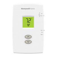
Installing Discharge and/or Return
Air Temperature Sensors
(T10+ only)
Use the following steps to mount the Discharge/Return
Air Sensors:
1. Attach plastic cover to the sensor probe.
2. Drill 1/4-inch hole for the sensor probe and mount it to
the ductwork with enclosed screws (see Fig. 67).
3. Connect wires to S1, S2, S3, or S4 terminals at the EIM
or S terminals at T10+ when EIM is not used.
4. Configure the T10+ thermostat for discharge and/or
return sensor.
Fig. 67. Mounting Discharge/Return Air Sensor.
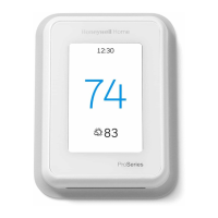
Installing Wired Indoor Sensor
C7189U1005 (10K) Wired Indoor Sensor
ISU setting 5000.
Use the following steps to mount the sensor:
1. Remove the cover from the remote sensor. See Fig. 68.
Fig. 68. Remove the cover.
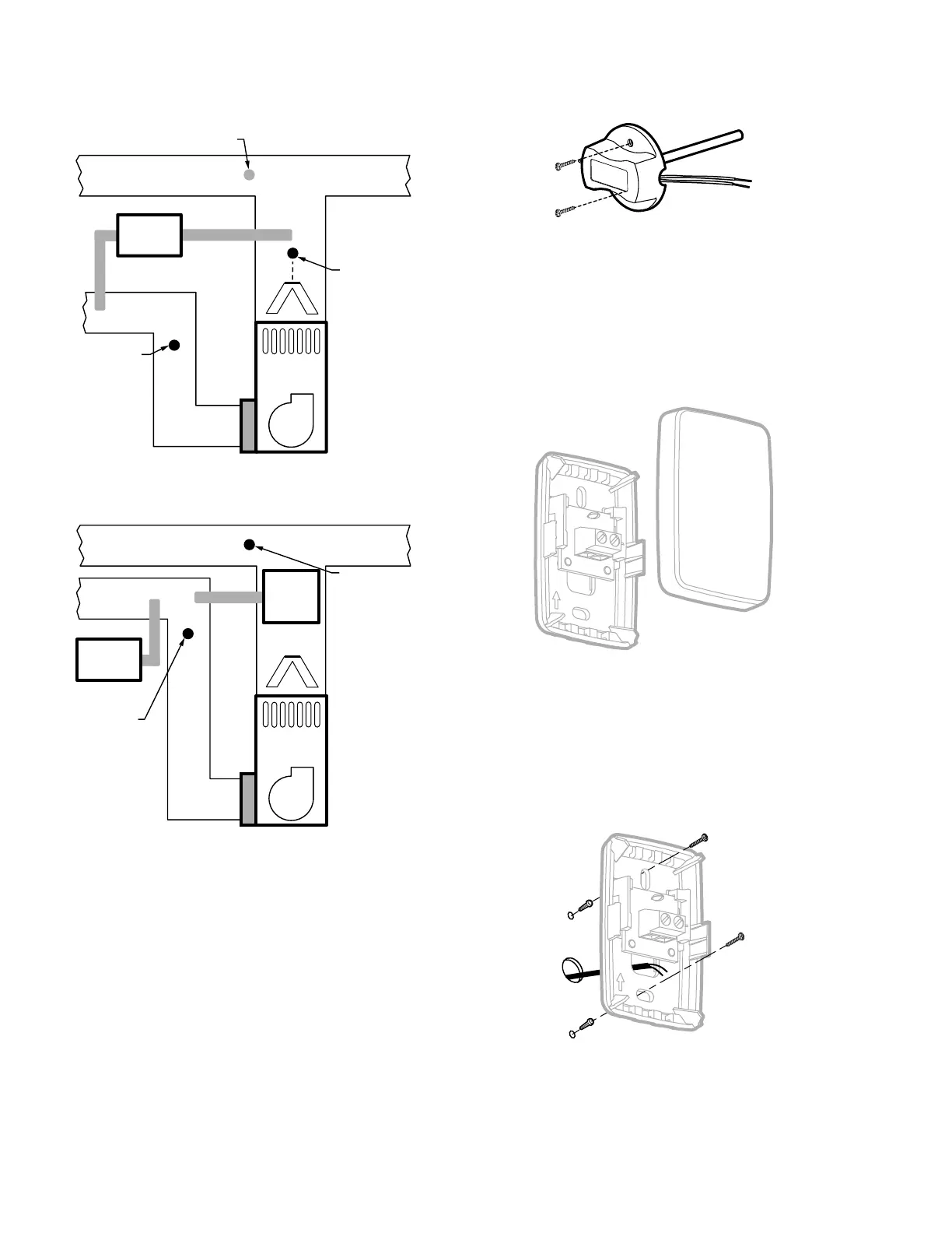
2. Pull wires through wire hole.
3. Position wallplate on wall, level and mark screw hole
positions with pencil.
4. Drill holes at marked positions, then tap in supplied wall
anchors.
5. Place wall plate over anchors, insert and tighten
mounting screws see Fig. 69.
Fig. 69. Mount wallplate to wall.
6. Replace the cover on the remote sensor.
M39062
HEAT
EXCHANGER
BLOWER
MOUNT RETURN
SENSOR HERE
DOWNSTREAM OF
DEHUMIDIFIER
ALTERNATE MOUNTING LOCATION
FOR DISCHARGE SENSOR
MOUNT
DISCHARGE
SENSOR HERE
ABOVE CENTER
OF A-COIL
UPSTREAM OF
DEHUMIDIFIER
DEHUMIDIFIER
MOUNT RETURN
SENSOR HERE
MOUNT DOWNSTREAM
OF BYPASS HUMIDIFIER,
DEHUMIDIFIER OR
VENTILATOR
HEAT
EXCHANGER
BLOWER
VENTILATOR
OR
DEHUMIDIFIER
MOUNT
DISCHARGE
SENSOR HERE
BYPASS
HUMIDIFIER
M33078A
M24056B
UP
M24057B
UP
 Loading...