9 33-00462—05
Table 8. Terminals on THM04R3000 Equipment Interface Module (EIM) Used With T10+ Models Only.
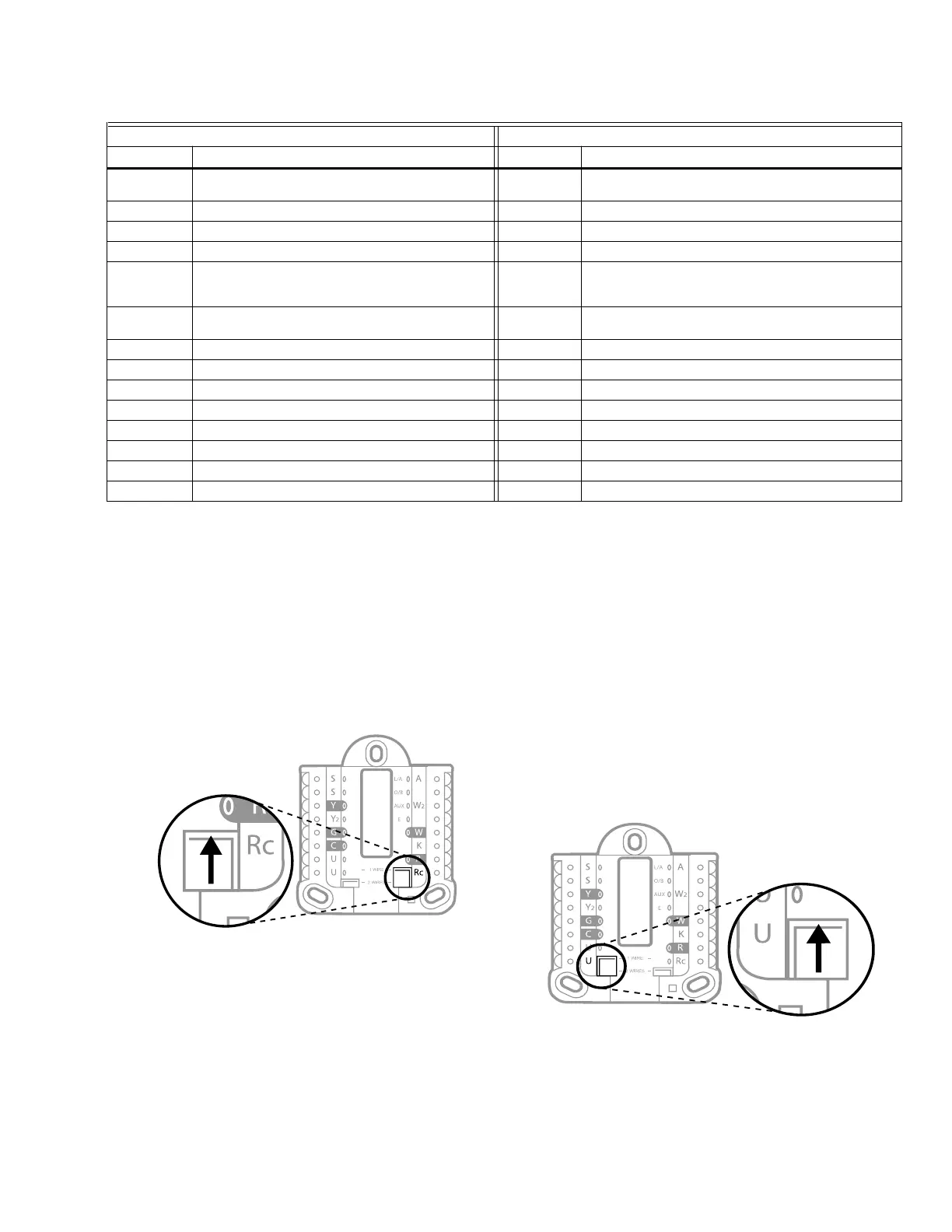
Setting Slider Tabs
Set R Slider Tab, see Fig. 13.
• Use built-in jumper (R Slider Tab) to differentiate
between one or two transformer systems.
• If there is only one R wire, and it is connected to the
R, Rc, or RH terminal on the old thermostat, set the
slider to the up position (1 wire).
• If there is one wire connected to the R terminal and
one wire connected to the Rc terminal, set the slider
to the down position (2 wires).
Fig. 13.
Set U Slider Tab, see Fig. 14.
• Use built-in jumper (U Slider Tab) for IAQ device.
• When the U Slider Tab is in the down position (2
wires) the U contacts are a dry set of contacts.
• If your IAQ device is powered by the cooling
transformer, move the U Slider Tab to the up
position (1 wire). When this is done, the lower U
terminal is internally jumped to the Rc terminal. In
this application, you would hook up one wire from
your IAQ device to the upper U terminal and the
other to the common side of the cooling transformer.
The 1 wire setting is most commonly used when
using a fresh air damper for ventilation or using low
speed fan for dehumidification.
• See wiring examples on the next page.
Fig. 14.
Conventional Systems Heat Pump Systems
Terminal Description Terminal Description
S1, S2, S3, S4
(Two of each)
Input for indoor sensor, outdoor sensor, Floor sensor,
RATS, DATS, or Dry Contact Alert
S1, S2, S3, S4
(Two of each)
Input for indoor sensor, outdoor sensor, Floor sensor,
RATS, DATS, or Dry Contact Alert
Y Compressor Stage 1 Y Compressor Stage 1
Y2 Compressor Stage 2 Y2 Compressor Stage 2
G Fan Relay G Fan Relay
C
Common from HVAC transformer when R is jumped to Rc
.
Common from separate transformer if R is not
jumpered
C
Common from HVAC transformer when R is jumped to Rc
.
Common from separate transformer if R is not
jumpered
U1, U2, U3
(Two of each)
Relay for humidifier, dehumidifier, or ventilator U1, U2, U3
(Two of each)
Relay for humidifier, dehumidifier, or ventilator
L Not used for conventional applications L Connect to compressor monitor
O/B Not used for conventional applications O/B Changeover valve for heat pumps
W1 Heat Stage 1 W1 Not used for heat pump applications
W2 Heat Stage 2 AUX1 Stage 1 of AUX/EM heat
W3 Heat Stage 3 AUX2 Stage 2 of AUX/EM heat
R 24V from transformer to power EIM R 24V from transformer to power EIM
Rc 24 VAC Cooling transformer Rc 24 VAC Cooling transformer
Rh 24 VAC Heat transformer Rh 24 VAC Heat transformer
 Loading...