17 33-00462—05
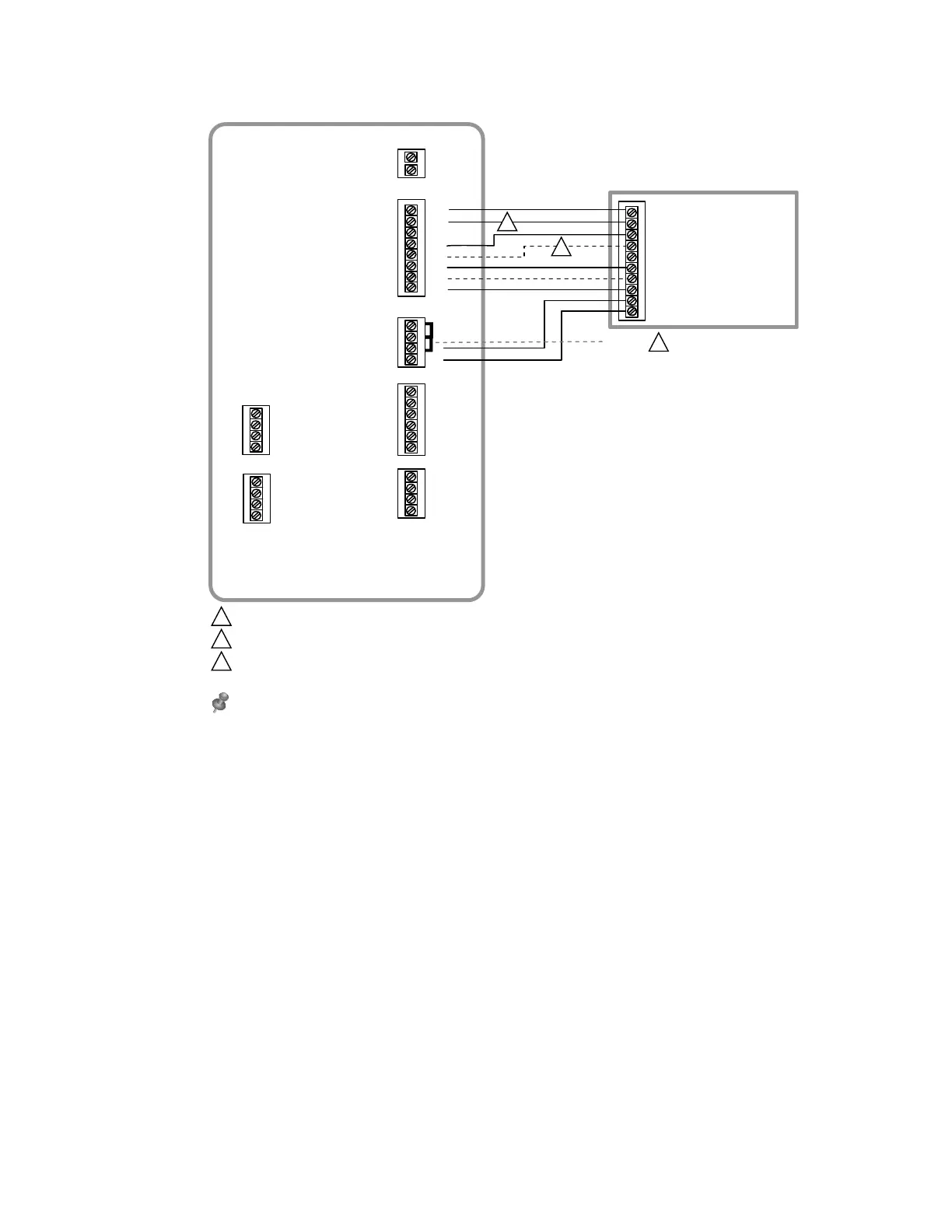
Fig. 36. Typical wiring of a heat pump system with up to four-stage heat and two-stage cool with one transformer
R
C
S4
S4
S3
S3
AUX1
AUX2
24 VAC TO
THERMOSTAT
U3
U3
U2
U2
U1
S2
S2
S1
S1
THM04R3000
Y2
G
U1
L
W1
W2
W3
Y1
RH
RC
R
C
SENSORS
SENSORS
DRY CONTACT OUTPUTS
24 VAC
POWER
O/B
HEAT PUMP / AIR-HANDLER
G (FAN)
R (24 VAC HOT)
AUX 1 (AUXILIARY HEAT)
AUX 2 (AUXILIARY HEAT STAGE 2)
Y1 (COMPRESSOR STAGE 1)
Y2 (COMPRESSOR STAGE 2)
C (24 VAC COMMON)
JUMPERS
11
L (SYSTEM FAULT MONITOR)
O (CHANGEOVER VALVE)
1
2
3
REMOVE JUMPER(S) IF USING SEPARATE TRANSFORMERS.
THE CHANGEOVER VALVE WILL BE LABELED O IF ENERGIZED IN COOL OR B IF ENERGIZED IN HEAT.
THE AUXILIARY HEAT STAGE(S) ARE LABELED DIFFERENTLY ON DIFFERENT HEAT PUMP AIR HANDLERS. MOST HEAT
PUMPS APPLICATIONS ONLY HAVE ONE STAGE OF AUXILIARY HEAT.
NOTE: SEE FOLLOWING PAGES FOR ADDITIONAL THERMOSTAT WIRING GUIDELINES FOR OTHER SYSTEM TYPES, SENSOR
WIRING, IAQ CONTROL, AND OTHER DRY CONTACT WIRING OPTIONS.
1
2
3
M38715
 Loading...