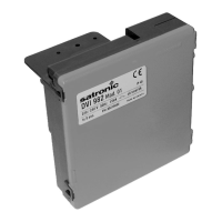
Verify that sufficient numbers of the following items
are on hand:
Racks (4-, 8- and 12-slot)
Power Supplies: 1 per rack or 2 per rack if redundant
powered rack.
C30/C50/C70 Controller Module or Scanner 1 port (1 per
rack)
Redundancy:
Each Controller Rack: 2 Power Supplies, 2 C75 CPUs,
1 Redundancy Switch Module.
Each I/O Rack: 1 Scanner dual-port module, 1 Power
Supply, 1 reserve Power Supply (optional), 1 Power
Status Module (optional)
I/O Modules (correct type for each configured slot)
Terminal Blocks, Barrier or Euro style, (1 for each I/O
Module)
Jumpers 2-position or 10-position, (for designated
Terminal Blocks)
Tie Wraps (1 or 2 for each Terminal Block)
I/O Label (one per terminal block, by module type)
Filler Block Cover (1 for each slot not occupied by an
I/O Module)
Blank label (1 for each Filler Block Cover)
Grounding Bars for I/O wiring shields (1 or 2 for each 4-
slots in each rack)
Wiring terminal lugs (for connecting I/O shields to
grounding bars)
Sheet metal screws, steel #10 or M4, for mounting racks
in enclosures (4 screws for 4-slot racks, 8 screws for 8- or
12-slot racks)

 Loading...


