AQ25A SERIES PROGRAMMABLE BOILER CONTROL PANELS
69-2119—02 4
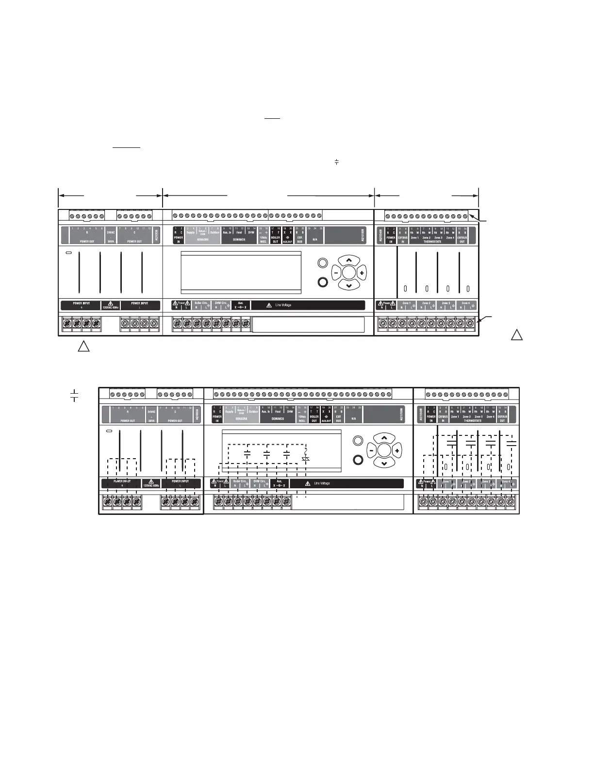
In general, the top terminals of the AQ2000 Series components
carry low voltage (24 Vac) power and the bottom terminals
carry line voltage (120 Vac) power. This is illustrated in Fig. 1.
The two exceptions to this are:
1. AQ15740B Zoning Module for use with zone valves with
end switches.
2. AQ15540B Zoning Module when used with low voltage
zone valves without
end switches.
For these the two exceptions, the bottom terminals of the
Transformer and Control Module carry line voltage (120 Vac),
but the bottom terminals of the Zoning Module will carry low
voltage (24 Vac) power.
The powered terminals on the bottom of the AQ2000 Series
Control Modules and Zoning Modules are connected internally
as shown in Fig. 2. The voltage supplied to the N and L
terminals is also available at the adjacent terminal pairs when
the hot ( ) relays are switched.
Fig. 1. AQ25A Series Programmable Boiler Control Panel layout (AQ25A42B shown).
Fig. 2. Internal wiring for AQ2000 Series components line voltage relays.
Menu
Home
OK
M27753
Zone 1
Zone 2 Zone 3
Zone 4
LOW
VOLTAGE
(24 V)
LINE
VOLTAGE
(120 V)
ZONING MODULE
TRANSFORMER
CONTROL MODULE
FOR THE AQ25A42B TERMINALS CAN BE LINE VOLTAGE (IF USED WITH PUMPS) OR LOW VOLTAGE (IF USED WITH ZONE VALVES)
1
1
M27754A
Zone 1
Zone 2 Zone 3
Zone 4
CONTACTS
SYMBOL
Menu
Home
OK

 Loading...


