AQ252 Universal Injection/Mixing Boiler Reset Control Panels
13 69-1986—02
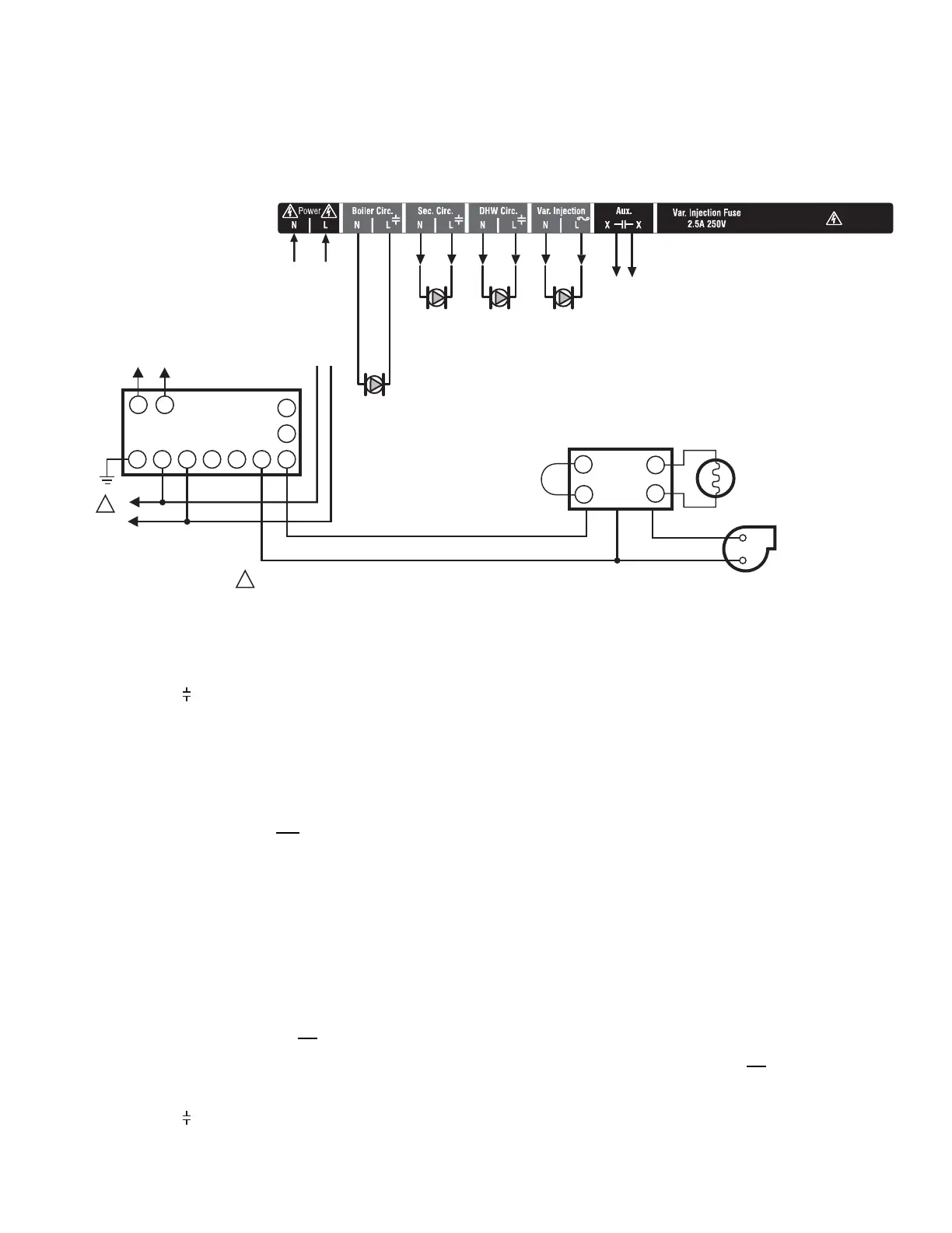
Step 5 – Line Voltage System Outputs
Refer to Fig. 15 and follow these steps to wire the devices to
the AQ252 Control Module.
“1. Boiler Pump”
“2. DHW Device”
“3. Line Voltage Rated Variable Injection Pump”
“4. Line Voltage Rated Aux Output (Aux. Pump)” on page 14
“5. Secondary Pump” on page 14
Fig. 15. Line Voltage Connections for AQ252.
1. Boiler Pump
Connect the N and L wires of the boiler loop pump to the N and
switched hot ( ) terminals of the line voltage Boiler output,
shown in Fig. 17 on page 14. The ground wire of the pump can
be connected to any of the 8 ground screw terminals located
on the back surface of the Control Panel enclosure.
The boiler pump contacts are made after any one of the
following occur:
• A call for heat has occurred from any heating zone.
• The Heat input is shorted on terminals 13 and 14.
• The DHW input is shorted and
the DHW type is configured
as a valve.
The pump is delayed for the FIRE DELAY programmed in the
EQUIPMENT SETUP > BOILER OPERATION sub-menu (see
Fig. 25 on page 41). The boiler pump and the last zone calling
remain “On,” in order to move heat out of the boiler for the
period of time programmed in the Purge time menu under the
fire delay. Manually adjusting thermostats affects the operation
of this software, so it can not be tested manually. You must
observe it under normal operating conditions.
NOTE: If the AQ252 is connected to a modulating
condensing boiler, the boiler pump may need to be
connected to the boiler, not
the AQ252. Confirm this
with the boiler’s installation manual.
2. DHW Device
Wire the DHW pump or line voltage zone valve to the N and
switched hot ( ) terminals of the DHW output, as shown in
Fig. 17 on page 14.
If using a low voltage zone valve, wire the primary of a spud-
mounted transformer (115V to 24V) to the DHW line voltage
contacts and connect the low voltage zone valve to the
secondary terminals of this transformer. A spud-mounted
transformer may be located in one of the conduit knockouts on
the bottom of the AQ252 Control Panel.
Alternatively, a 24 Vac zone valve can be connected to the
Aux. pump line voltage-rated dry contacts, which can be
configured to close on a DHW call. This configuration is
defined in the Installer Equipment Setup menu beginning on
page 32.
The DHW contacts are made when the DHW inputs on
terminals 15 and 16 are shorted by the controlling Aquastat.
This is a line voltage output designed to go to the DHW pump.
If 24 Vac is needed for a low voltage valve, you can mount a
step-down transformer on the conduit opening and wire the
valve from the transformer. When DHW is enabled, the system
has a 30 minute priority over all calls for heat. After 30 minutes,
calls for heat are added back in to the operation for 30 minutes
and then turned off again. This repeats until the DHW is
satisfied.
NOTE: If the AQ252 is connected to a modulating
condensing boiler, the DHW pump will probably need
to be connected to the boiler, not
the AQ252. Confirm
this with the boiler’s installation manual.
3. Line Voltage Rated Variable Injection Pump
The terminals for the variable injection pump are line voltage
rated and protected by an external fuse. A standard pump is
controlled by the output of these terminals.
ZC
ZR
B1
B2
C1
C2
L1
L2
TT
G
L8148, L7148
R8184A, R7184
BURNER AND
IGNITION
C554
F
F
T
T
BLACK
WHITE
ORANGE
POWER SUPPLY. PROVIDE DISCONNECT MEANS AND OVERLOAD PROTECTION AS REQUIRED.
L1
(HOT)
L2
1
1
TO AUXILIARY DEVICE
(INSTALLER-DEFINED)
BOILER
PUMP
M27692A
N
L
TO LINE VOLTAGE 120V
TERMINALS (N AND L) ON
BOTTOM OF TRANSFORMER
FROM LINE VOLTAGE 120V
TERMINALS (N AND L) ON
BOTTOM OF TRANSFORMER
TO BOILER
TERMINALS 22-23
ON TOP OF AQ15200B
CONTROL MODULE

 Loading...


