AQ25A SERIES PROGRAMMABLE BOILER CONTROL PANELS
69-2119—02 6
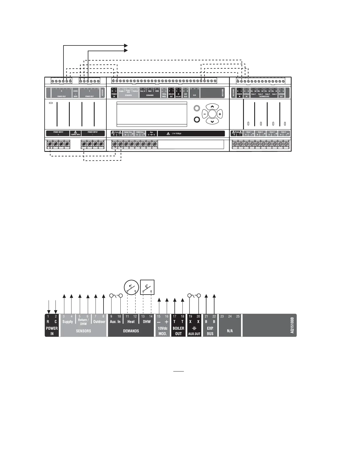
Fig. 4. Wiring sequence.
Step 1 – Transformer Wiring
Factory pre-wiring of the Control Panels is shown as dotted
lines in Fig. 4.
In addition to the pre-wiring, run low voltage jumper wires from
available R and C terminals to the R and C terminals of any
Expansion Zoning Panel.
Step 2 – Control Panel Wiring
Wire the Temperature Sensors, System Demands, Low
Voltage Outputs, and Communication Bus (Refer to Fig. 5 for
wiring terminals on the top of the AQ25A):
• “Temperature Sensor Wiring”
• “System Demands Wiring” on page 7
• “Low Voltage Outputs Wiring” on page 8
• “Communication Bus Wiring” on page 8
Fig. 5. Low voltage wiring for the AQ15A10B Control Module.
Temperature Sensor Wiring
Connect the lead wires of each sensor to the corresponding
terminals on top of the AQ15A Control Module. See Fig. 5.
The Boiler Supply and Return sensors can be installed either
as strap-on sensors or inserted into an immersion well that is
packed with thermally conductive paste.
BOILER SUPPLY AND RETURN SENSORS.
Both
the Supply and Return Sensors should be installed on the
supply and return piping of the boiler for proper operation of
the AQ25A Control Panel. Even if the AQ25A is connected to a
modulating condensing boiler with its own supply and/or return
sensors, the AQ25A’s sensors should still be installed for the
control to operate.
The Boiler Supply water sensor should be installed on the
supply piping close to the exit port of the boiler, using one of
the AQ12C11 strap-on sensors supplied with the AQ25A (see
Fig. 6 on page 7).
M27755
Zone 1
Zone 2 Zone 3
Zone 4
STEP 1 STEP 2 STEP 3
STEP 4STEP 5STEP 6
TO EXPANSION ZONING MODULES
(IF INSTALLED)
Menu
Home
OK
M27756
TO BOILER SUPPLY SENSOR
TO BOILER RETURN SENSOR
TO OUTDOOR SENSOR
IN FROM “R” TERMINAL ON
TRANSFORMER MODULE
(FACTORY-WIRED)
TO “T-T” TERMINALS ON
BOILER AQUASTAT
TO B-B “EXP.BUS IN”
TERMINALS ON CONNECTED
ZONING MODULE
TO SETPOINT LOAD
(OPTIONAL)
TO DHW AQUASTAT
IN FROM “C” TERMINAL
ON TRANSFORMER MODULE
(FACTORY-WIRED)
TO LOW VOLTAGE AUXILIAR
DEVICE (OPTIONAL)
TO AUXILIARY INPUT
SWITCH (OPTIONAL)
TO MODULATING INPUT
ON BOILER

 Loading...


