AQ251 SERIES BOILER RESET CONTROL PANELS
33 69-1974—04
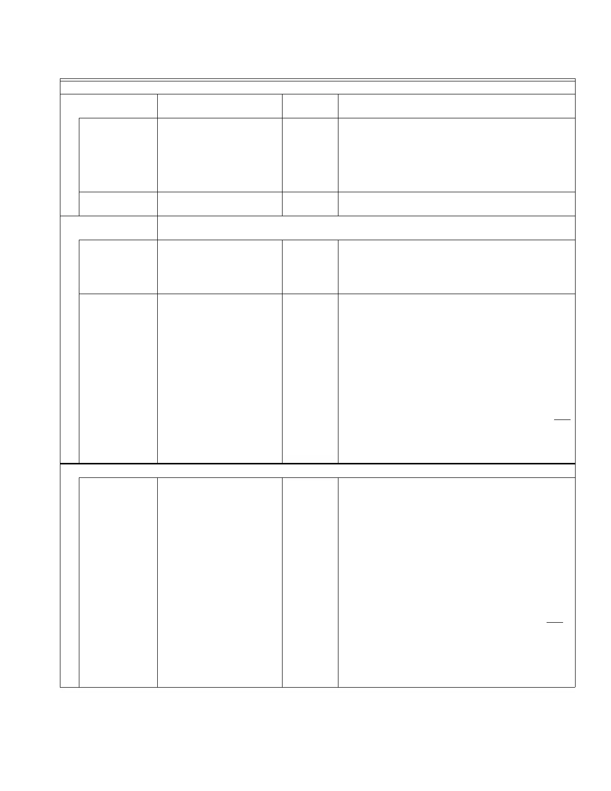
PRIO.OVER YES / NO NO Displays only if HT DMND PRIO = YES.
Selects whether (following a 30 minute uninterrupted call
for Heat Demand) the priority given to the Heat Demand
can be overridden to minimize the chance of freeze up or
excessive cool down of the space heating zones.
• YES = On = Allow Heat Demand Priority override.
• NO = Off = Do not allow Heat Demand Priority override.
ZONING VALVES
TIME TO OPEN
0 - 230
(seconds)
15
(seconds)
Time required for the zone valves installed on space
heating zones to fully open.
AUXILIARY I/O
Settings which the AQ251 uses to control the system based on input to the AUX. IN terminals or
to control the activation of the AUX.OUT and AUX.PUMP outputs.
AUX.IN
(optional)
SETBACK / VACANCY /
EM. SHUT / NONE
SETBACK Based on the setting chosen, the AQ251 sets the system in
one of 3 different levels of setback for as long as the Aux.
In terminals are shorted. Refer to instruction sheet for
AQ1000 thermostat (69- 2005EF) for setting the Vacancy
(Freeze Protection) temperature setpoint.
AUX.OUT
(optional)
BOILER / SETBACK /
ZONE OP. / ALARM /
AUX.IN / DHW IN / HEAT IN /
HT DMND / COOL / NONE
BOILER Based on the setting chosen, the AQ251 closes the AUX.
Out dry contact terminals when:
• BOILER: The boiler pump energizes.
• SETBACK: The system program is in setback mode
(either SLEEP or LEAVE).
• ZONE OP.: The end switch of a zone valve connected
to a Zoning Module closes or a zone pump energizes.
• ALARM: An alarm is detected on the system.
• AUX.IN, DHW IN, HEAT IN, or HEAT DMND: An input
signal is detected on the respective terminals.
• COOL: There is a call for cooling from a programmable
AQ1000 thermostat. The COOL option is available only
if central A/C is present; see the “A/C SETTINGSa” and
“A/C EQUIP CONFIG” menu options in this table.
• NONE: indicates that the Aux Out terminals are not
used.
AUXILIARY I/O (continued)
AUX.PUMP
(optional)
BOILER / GROUP / OCC /
BYPASS / FAN / NONE /
AUX.IN / DHW IN / HEAT IN /
HT DMND
BOILER Based on the setting chosen, the AQ251 closes the Aux.
Pump dry contacts when:
• BOILER: The boiler pump energizes.
• GROUP: Any of the thermostats in a Group of zones
(identified by the Zoning Module's DIP switch #7 [AUX]
being switched to YES) energize.
• OCC: The system program is in Occupied mode (either
WAKE or RETRN).
• BYPASS: The boiler return sensor measures a water
temperature less than the value defined for the
EQUIPMENT SETUP > BOILER SETTING > MIN
RETURN setting.
• FAN: There is a call for cooling from a programmable
AQ1000 thermostat. The FAN option is available only
if
central A/C is present; see the “A/C SETTINGSa” and
“A/C EQUIP CONFIG” menu options in this table
• AUX.IN, DHW IN, HEAT IN, or HEAT DMND: An input
signal is detected on the respective terminals.
• NONE: indicates that the Aux Pump terminals are not
used.
Table 6. Installer Menu – Equipment Setup. (Continued)
EQUIPMENT SETUP
Menu Option Range
Factory
Default Description

 Loading...


