34
FireLite SLC Wiring Manual — P/N 51309:R3 7/29/2019
Monitor Modules MMF-300 Wiring Diagrams
5.3 MMF-300 Wiring Diagrams
Following are wiring diagrams that depict NFPA Class B and Class A Initiating Device Circuits (IDCs) using MMF-300 monitor mod-
ules.
The Initiating Device Circuit (IDC) is supervised and current-limited to 210 microamperes @ 24 VDC (nominal).
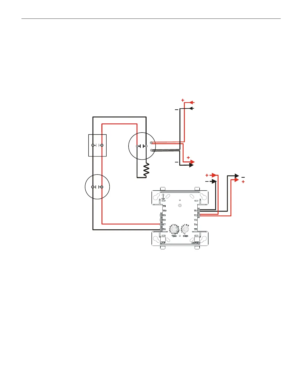
5.3.1 Wiring a NFPA Class B IDC with an MMF-300
Connect the SLC wiring to the module terminals 1 (–) and 2 (+).
Each module takes one address on the SLC. Use the rotary switches on the module to set it to the required SLC address. Refer to “Setting
an SLC address for a Single Point Module” on page 33.
The figure below shows typical wiring for a supervised and power-limited NFPA Class B IDC using an MMF-300 module.
• Refer to the Device Compatibility Document for compatible smoke detectors.
• See “Power Considerations” on page 63 for information on supervising 24 VDC power.
47K ELR
(supplied
with module)
Heat
detector
SLC
MMF-300
IDC
24 VDC Power
Filtered, Regulated,
Resettable
24 VDC
Four-wire
Detector Base
Manual pull
station
From Supply
To Next IDC
or
Supervision Device
SLC-idcB1tpH.wmf
Figure 5.9 Typical Class B IDC Wiring with an MMF-300
 Loading...


