48
FireLite SLC Wiring Manual — P/N 51309:R3 7/29/2019
Control Modules Wiring a CMF-300-6 Module
6.5 Wiring a CMF-300-6 Module
This section contains basic instructions and diagrams for wiring a Signaling Line Circuit with a CMF-300-6 as a Notification Appliance
Circuit (NAC).
For more detailed information on wiring a CMF-300-6 Control Module, refer to the Installation Instructions provided with the module.
Included in these instructions are wiring diagrams concerning a single power supply being shared by multiple NACs and audio NAC
configurations.
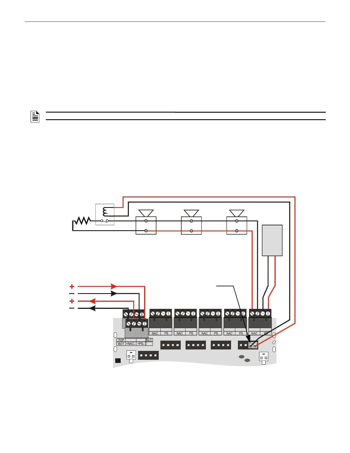
6.5.1 Wiring a Class B NAC (Two-Wire)
A supervised and power-limited NFPA Class B NAC with a single power supply dedicated to a single NAC using a CMF-300-6 module.
Polarized alarm notification appliances are shown connected to the module in a two-wire configuration.
• See “Power Considerations” on page 63 for information on monitoring 24 VDC power.
• Each module can control 2 amps of resistive load (on electronic devices) or 1 amp of inductive load (on mechanical bells and
horns).
• 24 VDC power must be provided from a UL listed power supply for fire protection use.
• A power supervision relay is required only on the last module of the power run.
• Do not T-tap or branch a Class B circuit.
• Terminate the circuit across the last device using an End-of-Line Resistor 47K, 1/2-watt,
P/N SSD A2143-00 (ELR-47K in Canada).
• Do not loop wiring under the screw terminals of any notification appliance. To maintain supervision, break the wire run at each
device.
NOTE: Refer to the Device Compatibility Document for compatible notification appliances and relays.
– +
– +
T10
T1
+1
+2
+3
+4
+5
T0
+0
T2
T3
T4
T5
T11
T12
T13
T14
T15
T16
24 VDC notification appliances
NAC Out
24 VDC
nonresettable
power
SLC-nacY2.wmf
Power Supervision
Relay
(EOLR-1)
SLC
CMF-300-6
ELR 47K,
1/2-watt
Relay Connector Assembly
Figure 6.5 NFPA Class B Notification Appliance Circuit
 Loading...


